Measuring the location of objects arranged on a surface, using multi-camera photogrammetry

a technology of photogrammetry and objects, applied in image analysis, instruments, computing, etc., can solve the problems of inconvenient use of electroencephalographic sensors, inconvenient use of methods, and inability to accurately measure the location of objects on a surface, etc., to achieve the effect of improving clarity

Active Publication Date: 2007-03-13
MAGSTIM GRP INC
View PDF14 Cites 32 Cited by
  • Summary
  • Abstract
  • Description
  • Claims
  • Application Information

AI Technical Summary

Problems solved by technology

This method is accurate but time-consuming, and may be susceptible to artifacts caused by metal objects in the vicinity of the subject.
This method is also time-consuming and impractical, especially with high-density electrode systems such as the Geodesic Sensor Net (our U.S. Pat. No. 5,291,888.)
However, these means are not useful with electroencephalographic sensors, except when used in conjunction with an MEG system.
However, in some important respects, this existing art is inadequate to meet the needs of EEG sensor localization.
However, they do not appear to have realized that a minimal structure necessary to completely surround a regular convex object (such as a human head) is only eleven cameras in an icosahedral gantry.
This choice results in a widely spaced set of cameras (with a dihedral angle of approximately sixty degrees), leading to another set of novel problems.
However, at very large angles this becomes problematic, because the varying angles result in varying amounts of local foreshortening of the image.
The problem is further exacerbated by the fact that these local correlation algorithms also assume a locally planar surface containing the objects under observation; in our case the shape of the head is strongly curved.
However, we are interested in precisely locating the centers of the sensor objects, and with a structured light system there can be no guarantee that any particular sensor will have its shape fully characterized with adequate precision.
Also, it is difficult to imagine the extension of the “structured light” paradigm, into the requirement of multiple simultaneous viewpoints surrounding the head.

Method used


Image

  • Measuring the location of objects arranged on a surface, using multi-camera photogrammetry
  • Measuring the location of objects arranged on a surface, using multi-camera photogrammetry
  • Measuring the location of objects arranged on a surface, using multi-camera photogrammetry

Examples


Embodiment Construction

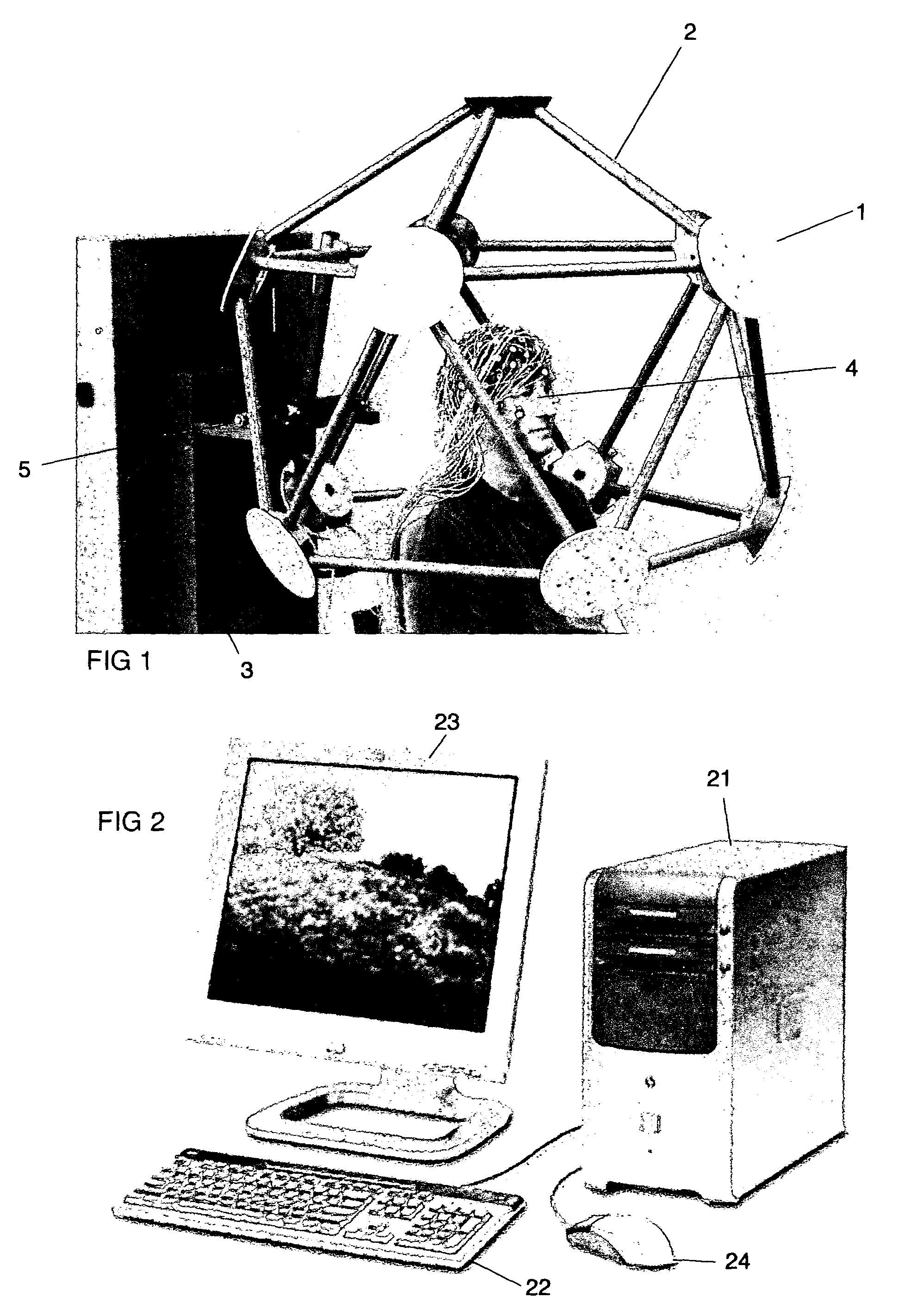
[0024]The preferred embodiment of our multi-camera photogrammetry apparatus is shown in FIG. 1. It consists of eleven cameras 1 arranged in an icosahedral geodesic structure 2. In this figure, a rolling motorized lifting and supporting structure 3 is used to position the camera gantry over the subject 4. The gantry is supported on a pivoting rod 5, and the gantry may simply be lifted upwards to allow the subject to enter or exit the system. The eleven cameras are connected to a computing means shown in FIG. 2, with a central processing unit (CPU) 21, keyboard 22, graphical display device 23 and mouse or other pointing device 24.

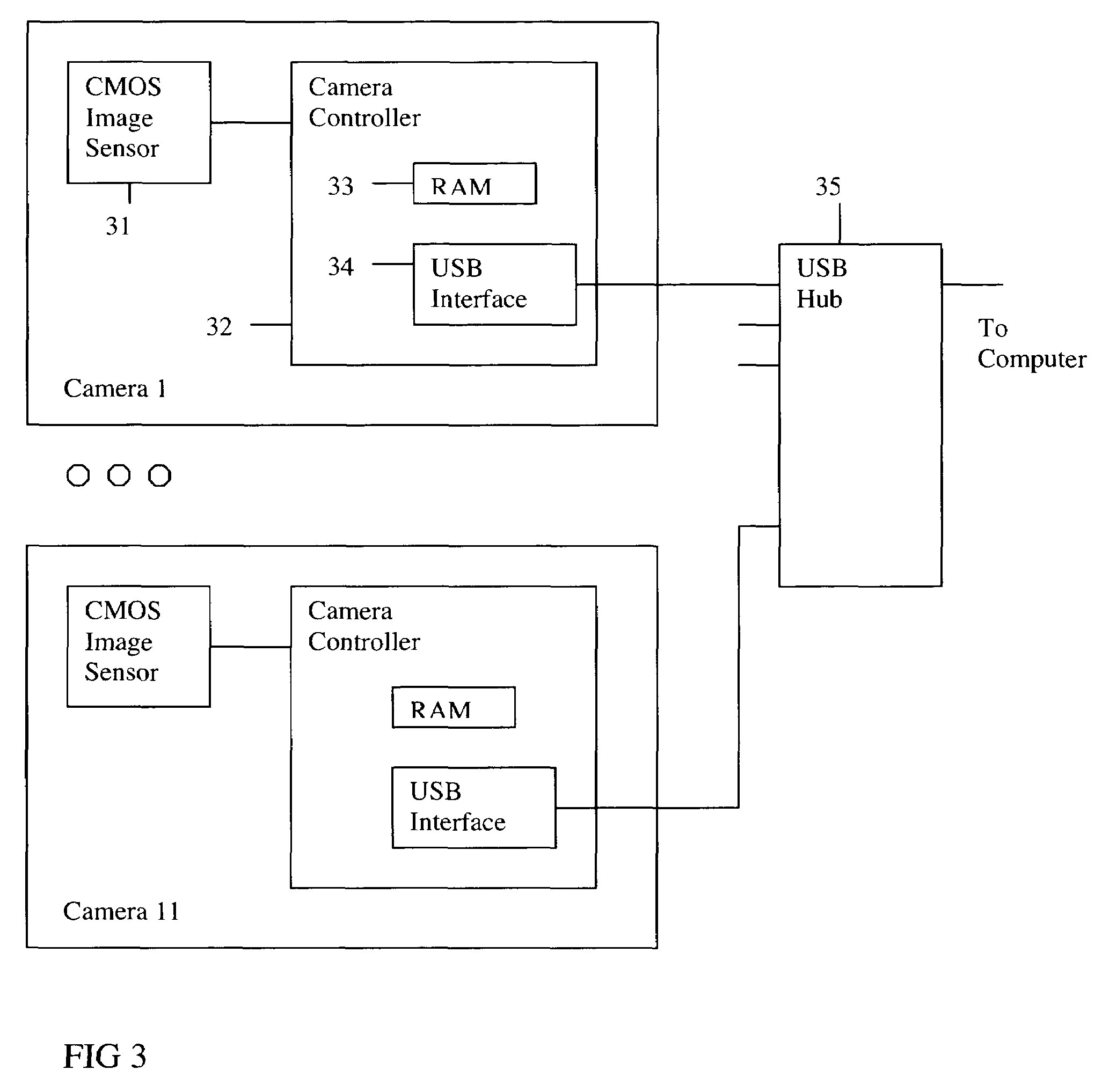
[0025]The preferred embodiment for the cameras (FIG. 3) uses inexpensive 640 by 480 pixel CMOS (Complementary Metal-Oxide Semiconductor) image sensors 31 to capture the video images. The sensors are supported by controller circuits 32 incorporating a local RAM (Random Acceess Memory) interface 33 for image buffering, and a USB (Universal Serial Bus) interface...


PUM


Abstract

A method and apparatus for measuring the location of objects arranged on a convex surface. A plurality of cameras is arranged in a stationary array about the surface, and is used to capture images of the objects. A parameterized model of the surface is developed using optimization techniques, and then the locations of the objects are established by triangulation. The method is applied to location of electrophysiological sensors on the head, for purposes of electroencephalographic source analysis, or for registration with other imaging modalities such as MRI (magnetic resonance imaging).

Description

BACKGROUND OF THE INVENTION[0001]In order to observe the dynamic physiology of the brain, a variety of sensors are required to be arranged around the head of a human (or animal) subject. These sensors are typically electrodes for detecting the electroencephalographic signal, but the may also include optical or magnetic sensors. For accurate analysis of the sources of physiological signals, it is also necessary to obtain precise measurements of the three-dimensional spatial coordinates of the sensors, so that they may be registered with images of the head made using other modalities (such as MRI or PET). Thus, a specialized art has developed for the purpose of measuring the locations of these sensors.[0002]In the previous art, one method uses a fixed transmitter of electromagnetic radiation, and a wand containing an electromagnetic detector which may be manually positioned at the location of each sensor in turn. The position of the wand may be evaluated by analysis of the signals rec...

Claims


Application Information

Patent Timeline
Patent Type & Authority Patents(United States)
IPC IPC(8): G06K9/00G06K9/46G06T7/00
CPCG06T7/0077G06T7/596
Inventor RUSSELL, GERALD STUCKER, DON MERIKSEN, K. JEFFREYOLIVIERI, ONOFRIO
Owner MAGSTIM GRP INC
Why Eureka
Try Eureka