Methods for driving electro-optic displays, and apparatus for use therein

a technology of electro-optic displays and apparatus, applied in the direction of electric digital data processing, instruments, computing, etc., can solve the problems of preventing their widespread use, inadequate service life of these displays, and giving rise to their own problems

Inactive Publication Date: 2007-03-20
E INK CORPORATION
View PDF216 Cites 508 Cited by
  • Summary
  • Abstract
  • Description
  • Claims
  • Application Information

AI Technical Summary

Problems solved by technology

Nevertheless, problems with the long-term image quality of these displays have prevented their widespread usage.
For example, particles that make up electrophoretic displays tend to settle, resulting in inadequate service-life for these displays.
However, such refreshing of the image may give rise to its own problems.
If an image is to be maintained for extended periods by applying refreshing pulses, these pulses need to be of the same polarity as the addressing pulse originally used to drive the relevant pixel of the display to the optical state being maintained, which results in a DC imbalanced drive scheme.
Furthermore, as discussed in the aforementioned U.S. Pat. Nos. 6,531,997 and 6,504,524, problems may be encountered, and the working lifetime of a display reduced, if the method used to drive the display does not result in zero, or near zero, net time-averaged applied electric field across the electro-optic medium.
Similar problems could be encountered with LCD's, but the insensitivity of such displays to the polarity of the applied electric field, and the consequent ability to reverse polarity at will, renders DC balance problems unimportant in LCD's.

Method used


Image

  • Methods for driving electro-optic displays, and apparatus for use therein
  • Methods for driving electro-optic displays, and apparatus for use therein
  • Methods for driving electro-optic displays, and apparatus for use therein

Examples


example 1

[0054]This Example uses displays containing an encapsulated dual particle opposite charge type medium comprising a polymer-coated titania white particle and a polymer-coated black particle with an uncolored suspending fluid. The displays were prepared substantially according to “Method B” described in Paragraphs [0061]–[0068] of the aforementioned 2002 / 0180687.

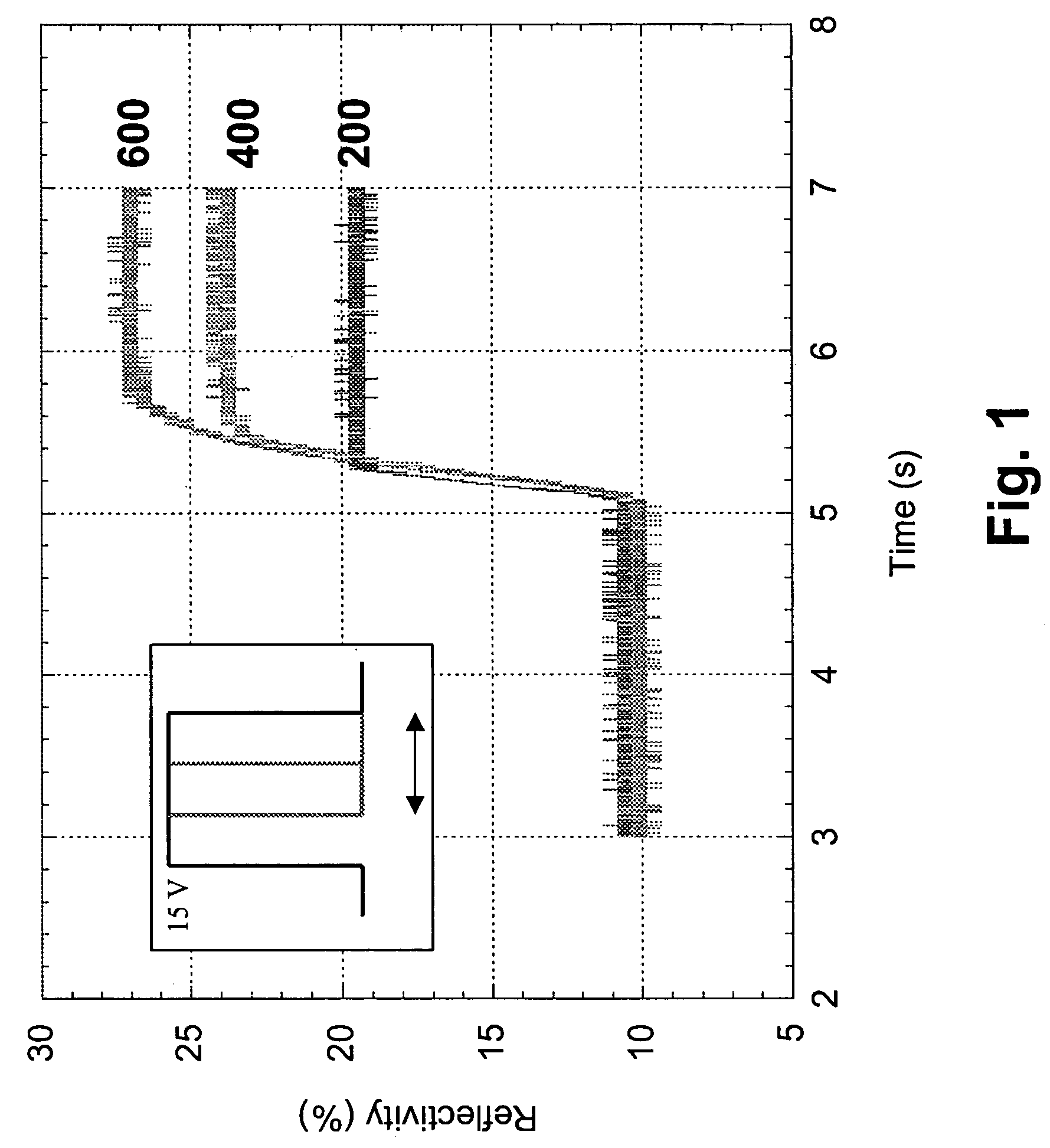
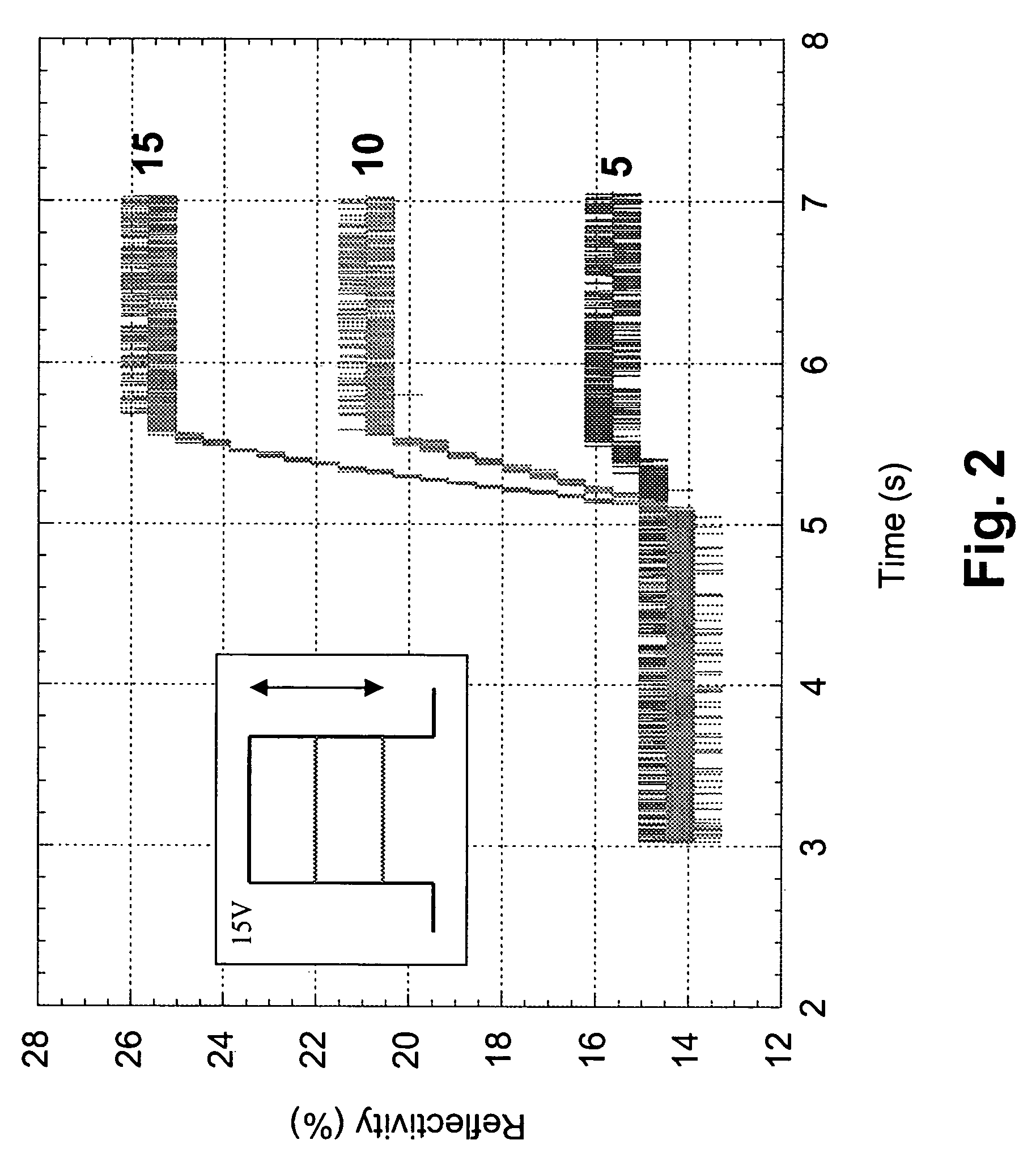
[0055]The displays prepared as described above, which contained multiple pixels, could be switched between their black and white optical states using addressing pulses of ±15 V for 500 msec. The displays had only limited bistability, the time necessary for the white optical state to change by 2 L* units being only about 15 sec. at ambient temperature. However, it was determined empirically that the white and black optical states could be maintained indefinitely by applying short refresh pulses of ±15 V for 4 sec / min, a duty cycle of approximately 6.7 percent. To provide a realistic test and avoid flicker in a standard image (c...


PUM

PropertyMeasurementUnit
frequencyaaaaaaaaaa
voltageaaaaaaaaaa
optical stateaaaaaaaaaa

Abstract

A method for addressing a bistable electro-optic display having at least one pixel comprises applying an addressing pulse to drive the pixel to a first optical state; leaving the pixel undriven for a period of time, thereby permitting the pixel to assume a second optical state different from the first optical state; and applying to the pixel a refresh pulse which substantially restores the pixel to the first optical state, the refresh pulse being short relative to the addressing pulse.

Description

CROSS REFERENCE TO RELATED APPLICATIONS[0001]This application is a continuation-in-part of application Ser. No. 10 / 065,795, filed Nov. 20, 2002 (Publication No. 2003 / 0137521, now U.S. Pat. No. 7,012,600), which is itself is a continuation-in-part of application Ser. No. 09 / 561,424, filed Apr. 28, 2000 (now U.S. Pat. No. 6,531,997), which is itself a continuation-in-part of application Ser. No. 09 / 520,743, filed Mar. 8, 2000 (now U.S. Pat. No. 6,504,524). Application Ser. No. 10 / 065,795 also claims priority from the following Provisional Applications: (a) Ser. No. 60 / 319,007, filed Nov. 20, 2001; (b) Ser. No. 60 / 319,010, filed Nov. 21, 2001; (c) Ser. No. 60 / 319,034, filed Dec. 18, 2001; (d) Ser. No. 60 / 319,037, filed Dec. 20, 2001; and (e) Ser. No. 60 / 319,040, filed Dec. 21, 2001. This application also claims priority from application Ser. No. 60 / 319,315, filed Jun. 13, 2002 and application Ser. No. 60 / 319,321, filed Jun. 18, 2002. Application Ser. No. 09 / 561,424 also claims priority...

Claims


Application Information

Patent Timeline
Patent Type & Authority Patents(United States)
IPC IPC(8): H04N1/46G02F1/167G09G3/20G09G3/34
CPCG02F1/167G09G3/2011G09G3/344G09G3/2007G09G2380/02G09G3/2014G09G3/2018G09G3/2074G09G3/2077G09G3/3453G09G2300/08G09G2310/02G09G2310/0254G09G2310/027G09G2310/04G09G2310/06G09G2310/061G09G2310/063G09G2310/068G09G2320/0204G09G2320/0214G09G2320/0247G09G2320/0252G09G2320/0285G09G2320/041G09G2320/043G09G2330/021G09G2340/16
Inventor DANNER, GUY M.AMUNDSON, KARL R.ZEHNER, ROBERT W.ARANGO, ALEXI C.EWING, JAY BRITTON
Owner E INK CORPORATION
Why Eureka
Try Eureka