Flexible housing for an airbag module

a flexible housing and airbag technology, applied in the direction of screw, pedestrian/occupant safety arrangement, vehicle sub-unit features, etc., can solve the problems of adding weight to the airbag module, affecting the safety of passengers, etc., to achieve convenient venting of inflation gas and rapid and reliable inflation

Active Publication Date: 2007-03-27
AUTOLIV ASP INC
View PDF19 Cites 30 Cited by
  • Summary
  • Abstract
  • Description
  • Claims
  • Application Information

AI Technical Summary

Benefits of technology

[0008]The inflator has a main body with an axis and a diffuser that extends generally perpendicular to the axis. The first flap has a tongue and the second flap has a slit through which the tongue is inserted. The inflator is positioned between the two flaps. Each of the flaps has an orifice, and each of the flaps is wrapped about three-quarters of the way around the main body of the inflator to position the orifices near the diffuser. The orifices are inserted over the diffuser so that the diffuser retains the ends of the first and second flaps, thereby keeping the flaps and the inflator in place. The inflator has a recess between the main body and the diffuser. The orifices slide into engagement with the recess, and the relatively larger profile of the diffuser tends to keep the orifices from sliding free of the diffuser. The flaps serve as a barrier that separates the housing into an inflator retention portion and a cushion retention portion.
[0010]When a collision or impending collision is detected, the inflator deploys to produce inflation gas. The inflation gas is released into the cushion retention portion via the diffuser. The inflation gas pushes the cushion out of the housing and inflates the cushion by passing through the attachment throat and the inlet. The outer wall may have one or more vents through which inflation gas is able to exit the cushion and housing at a limited flow rate during deployment. The vents may serve to soften the inflated cushion and permit deflation by releasing gas into the instrument panel. Venting may thus be provided without contact of the inflation gas with vehicle occupants.
[0015]Through the use of airbag modules and associated methods of the present invention, airbag modules may be produced in an efficient and inexpensive manner by elimination of a rigid housing. Such airbag modules may provide rapid and reliable inflation, and may easily permit venting of inflation gas into the instrument panel of a vehicle, thereby avoiding contact of the inflation gas with vehicle occupants. Furthermore, the airbag module may be efficiently and cost-effectively manufactured. These and other features and advantages of the present invention will become more fully apparent from the following description and appended claims, or may be learned by the practice of the invention as set forth hereinafter.

Problems solved by technology

Unfortunately, the housing adds significantly to the cost of the airbag module.
Additionally, the inflator and the cushion must be inserted into and attached to the housing with procedures that can be relatively time consuming and labor intensive.
The housing also adds weight to the airbag module, thereby adding to the overall weight and fuel consumption of the vehicle.

Method used


Image

  • Flexible housing for an airbag module
  • Flexible housing for an airbag module
  • Flexible housing for an airbag module

Examples


Embodiment Construction

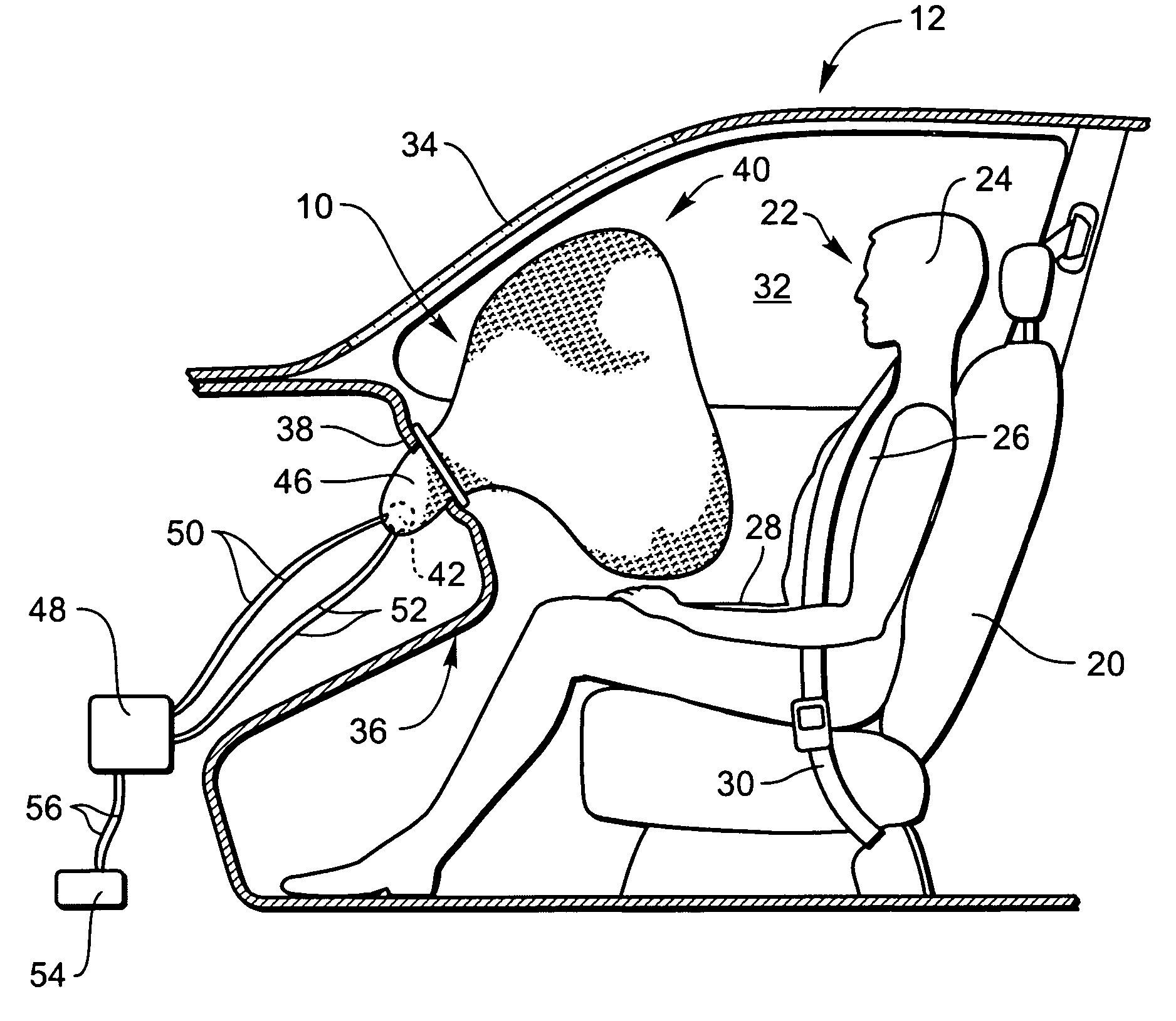
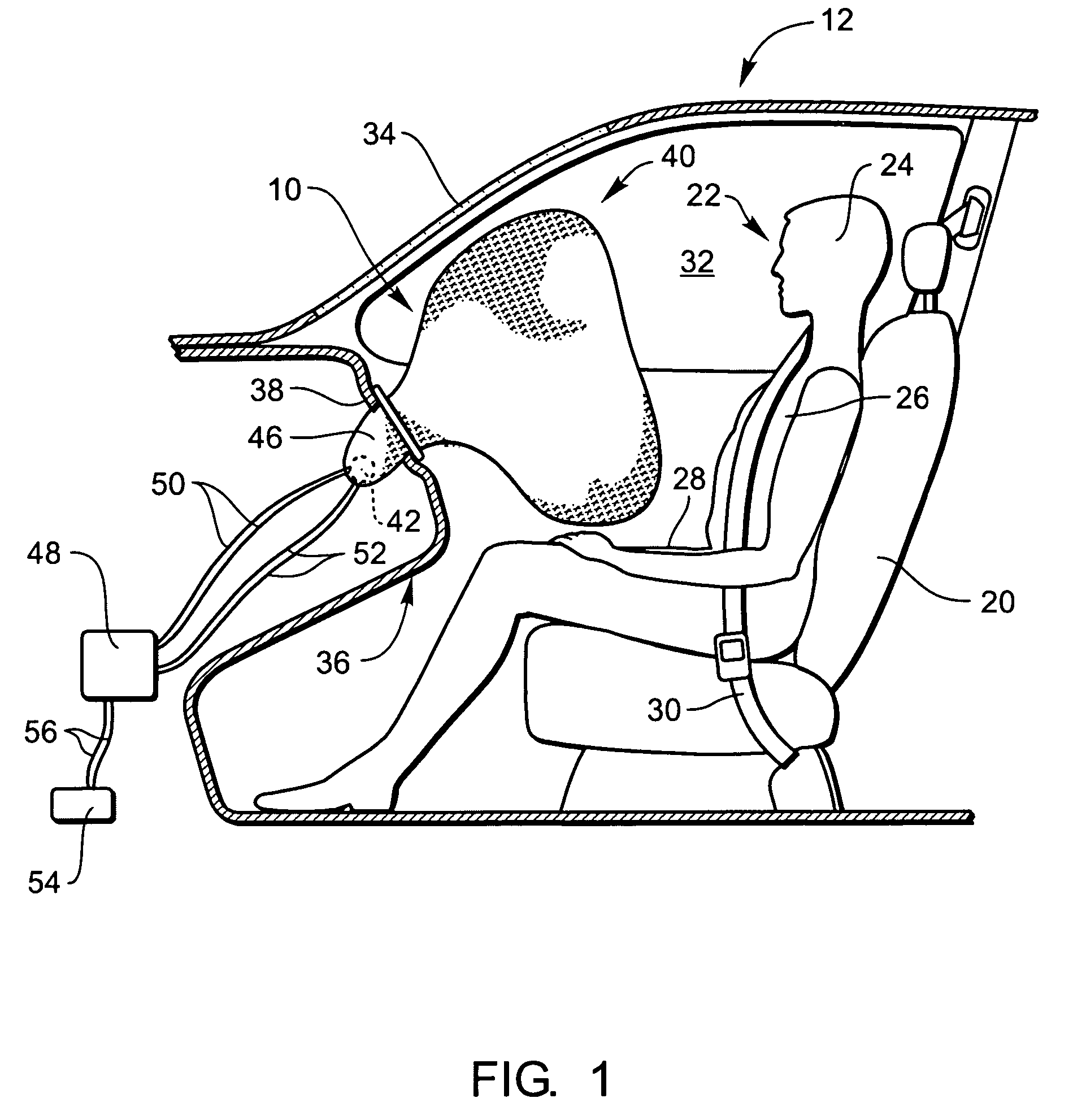
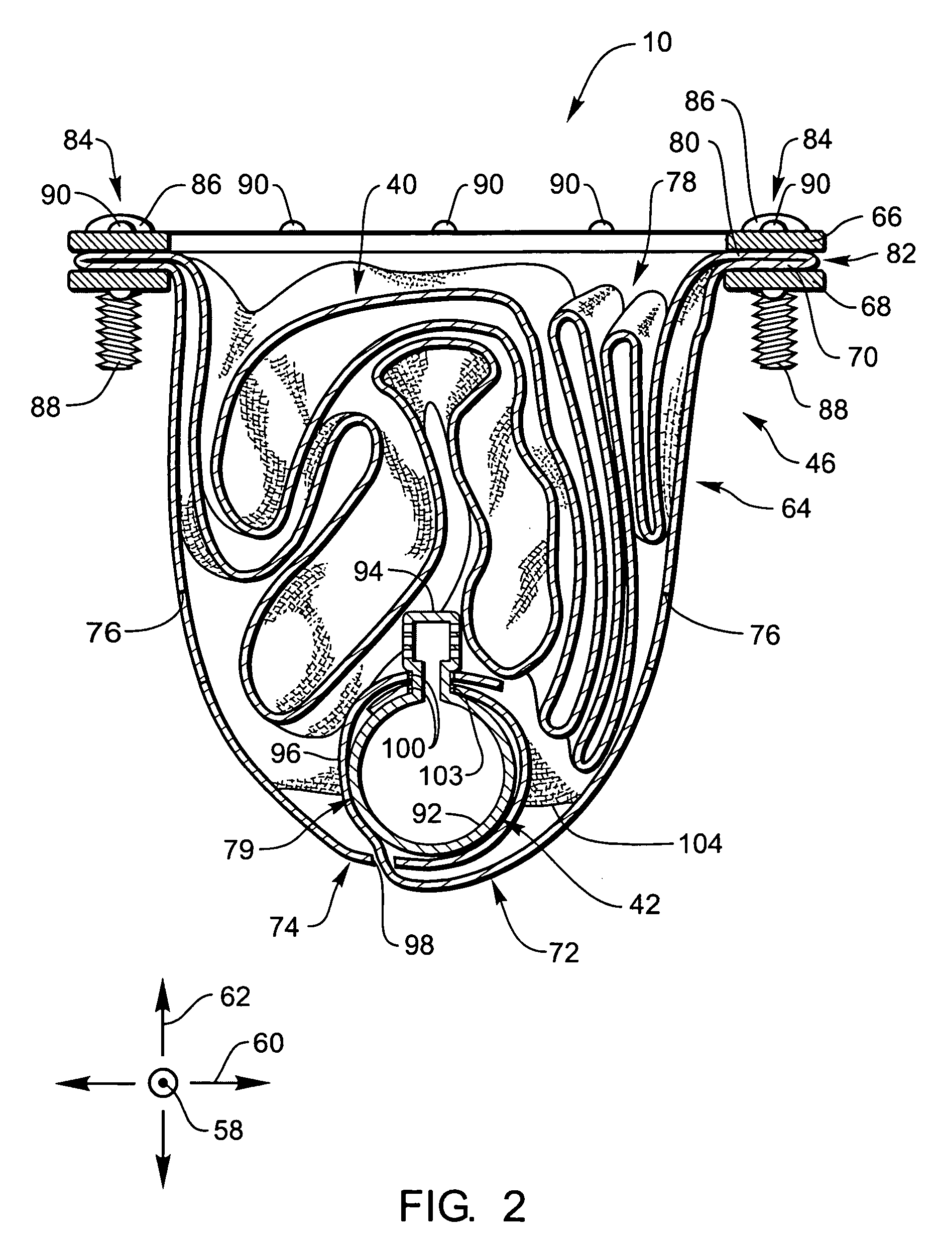
[0022]The presently preferred embodiments of the present invention will be best understood by reference to the drawings, wherein like parts are designated by like numerals throughout. It will be readily understood that the components of the present invention, as generally described and illustrated in the figures herein, could be arranged and designed in a wide variety of different configurations. Thus, the following more detailed description of the embodiments of the apparatus, system, and method of the present invention, as represented in FIGS. 1 through 5, is not intended to limit the scope of the invention, as claimed, but is merely representative of presently preferred embodiments of the invention.

[0023]For this application, the phrases “connected to,”“coupled to,” and “in communication with” refer to any form of interaction between two or more entities, including mechanical, electrical, magnetic, electromagnetic, and thermal interaction. The phrase “attached to” refers to a for...


PUM


Abstract

An airbag module may have an inflator, a cushion, and a housing that contains the inflator and the cushion. The housing has an outer wall formed of a flexible material and a bracket designed to be attached to a vehicle. During deployment, the cushion is expelled out of the housing through the bracket. The inflator remains in the housing and inflation gas is conveyed to the cushion through the housing. The inflator may be retained by flaps wrapped around the inflator and secured to a perpendicularly oriented diffuser of the inflator. Alternatively, the diffuser may extend through an orifice formed in a fabric wall within the housing, and retention portions of the outer wall may be wrapped around the opposite side of the inflator. The airbag module may be mounted in an instrument panel to provide front seat, passenger's side impact protection without requiring a rigid module housing.

Description

BACKGROUND OF THE INVENTION[0001]The inclusion of inflatable safety restraint devices, or airbags, is now a legal requirement for many new vehicles. Airbags are typically installed in the steering wheel and in the dashboard on the passenger's side of a car. Additionally, airbags may be installed to inflate beside vehicle occupants to provide side impact protection, in front of the knees to protect the knees from impact, or at other strategic locations.[0002]In the event of an accident, a sensor system within the vehicle senses an impact situation and triggers the ignition of an inflator. Inflation gases from the inflator fill the airbag cushions, which immediately inflate to protect the driver and / or passengers from impact against the interior surfaces of the vehicle. During normal vehicle operation, airbags are typically stowed behind covers to protect them from tampering and provide a more attractive interior facade for the vehicle.[0003]Passenger side frontal impact airbags are o...

Claims


Application Information

Patent Timeline
Patent Type & Authority Patents(United States)
IPC IPC(8): B60R21/16B60R21/217
CPCB60R21/2176B60R21/205B60R21/26B60R16/023B60R21/237F16B39/02B60R2021/2612B60Y2400/3042
Inventor LEWIS, ROBERT E.LEWIS, TRUDY C.LANG, GREGORY J.ROSE, LARRY D.
Owner AUTOLIV ASP INC
Why Eureka
Try Eureka