Specimen centrifuge system

a centrifuge and specimen technology, applied in the direction of centrifuges, instruments, specific gravity measurement, etc., can solve the problems of insufficient centrifuge capacity, insufficient centrifuge capacity, and inability to centrifuge a large number of specimens at once,

Active Publication Date: 2007-03-27
IDS CO LTD
View PDF10 Cites 16 Cited by
  • Summary
  • Abstract
  • Description
  • Claims
  • Application Information

AI Technical Summary

Benefits of technology

[0007]An object of the present invention is to provide a specimen centrifuge system having the following advantages.
[0010]3) Even though the number of specimen containers to be centrifuged is small or large, the system can centrifuge them with efficiency.

Problems solved by technology

However, the apparatus requires a relatively large space because the first and second rotors need to be arranged together on the horizontal surface.
The apparatus is difficult to centrifuge a number of specimens at once because its centrifuging capacity is restricted.
Even when the number of specimens to be centrifuged is very small, the apparatus needs to be operated, and it is therefore likely that energy will be consumed in vain.

Method used


Image

  • Specimen centrifuge system
  • Specimen centrifuge system
  • Specimen centrifuge system

Examples


first embodiment

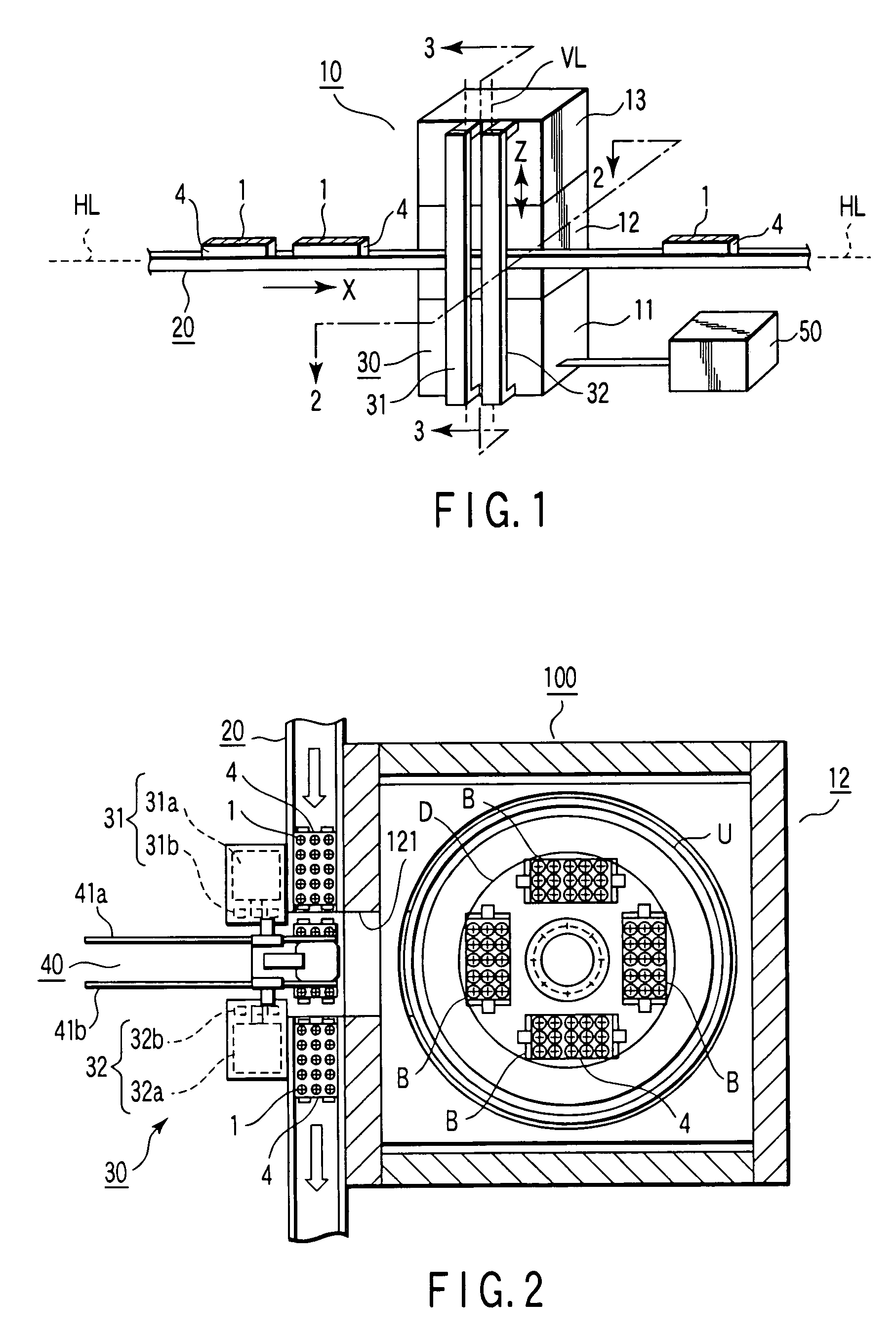
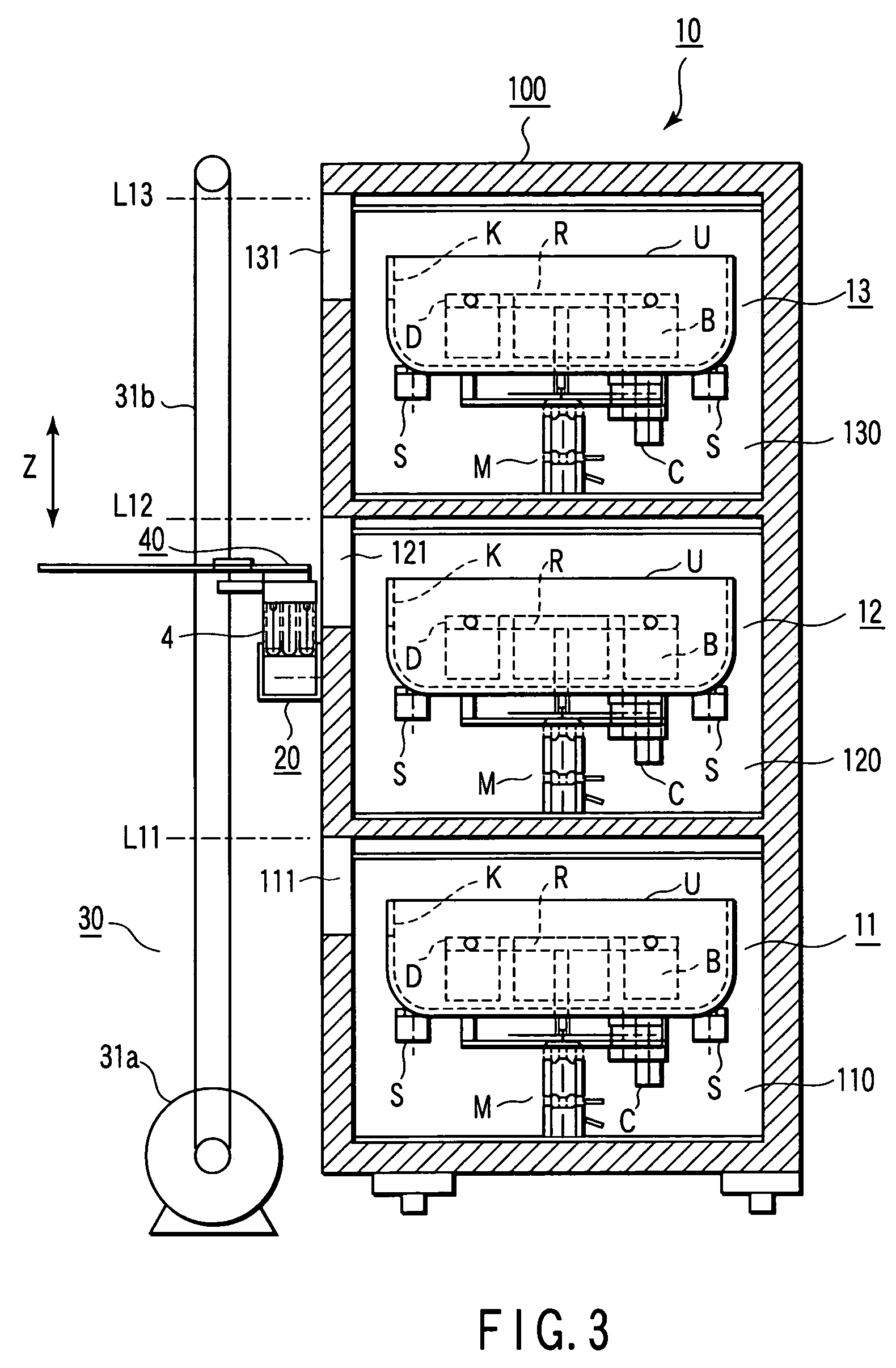
[0020]Referring to FIGS. 1 to 3, a specimen centrifuge system according to a first embodiment comprises a centrifuge unit 10. The centrifuge unit 10 includes a plurality of specimen centrifuges 11, 12 and 13 (three in the first embodiment). The specimen centrifuges are vertically stacked in a plurality of layers (three in the first embodiment).

[0021]The specimen centrifuges 11, 12 and 13 are stored in first to third cabinets 110, 120 and 130, respectively. These cabinets are formed by partitioning a rectangular parallelepiped housing 100 into three as shown in FIG. 3. The specimen centrifuges 11, 12 and 13 have the same configuration and each have an autobalance function.

[0022]Each of the specimen centrifuges 11, 12 and 13 has a motor M that is set up on the floor of the corresponding cabinet. Each of the centrifuges 11, 12 and 13 also has a rotor R that is rotated by the motor M, a protection frame U that surrounds the rotor R, a support member S that supports the protection frame ...

second embodiment

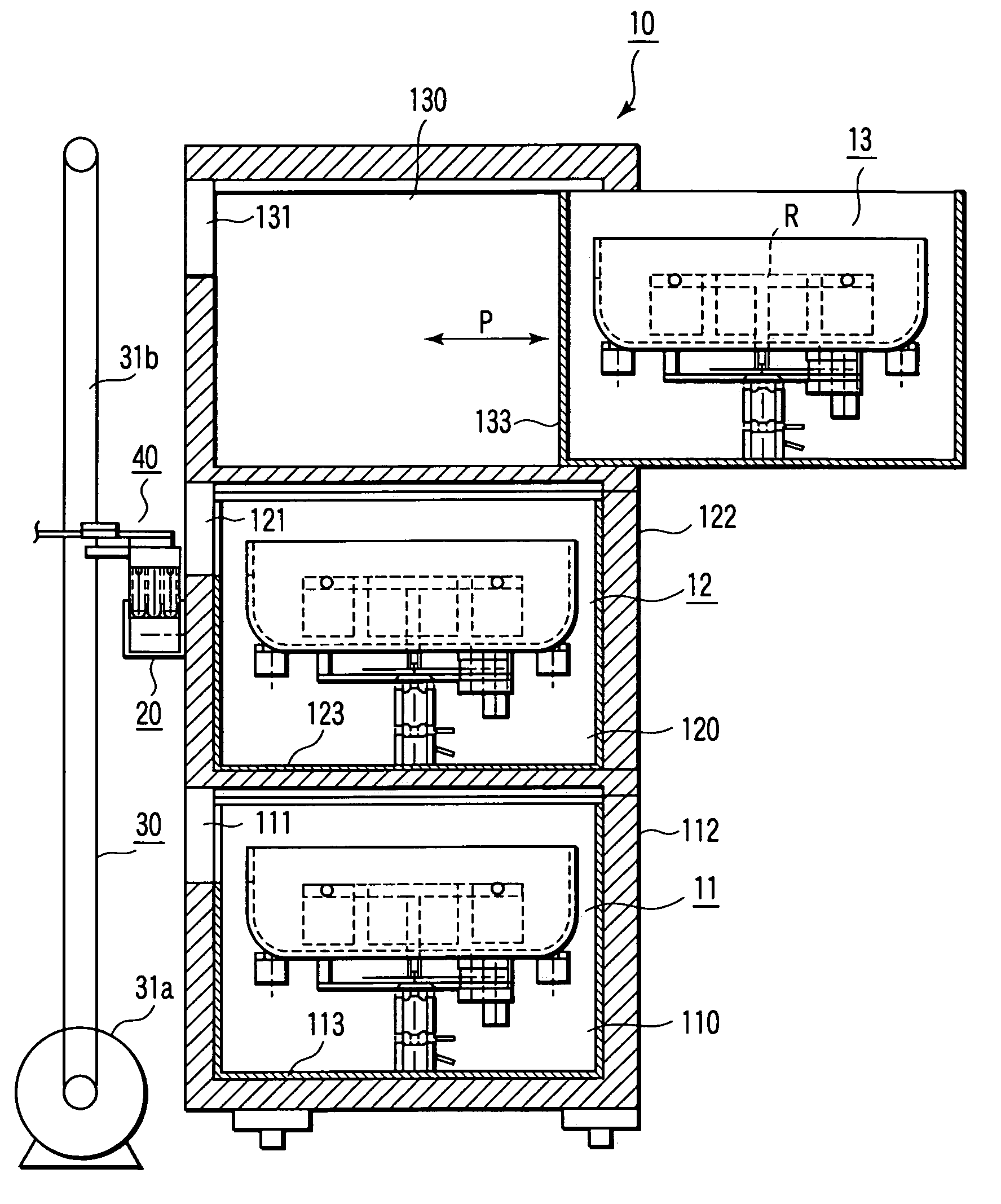
[0037]FIG. 7 is a longitudinal sectional view showing a centrifuge unit 10 according to a second embodiment of the present invention. The second embodiment differs from the first embodiment in which specimen centrifuges 11, 12 and 13 are insertably and removably stored in their respective cabinets 110, 120 and 130 stacked in layers. More specifically, the rear walls of the cabinets 110, 120 and 130 are formed of lids 112, 122 and 132 (not shown) that can freely be opened and closed. Inner boxes 113, 123 and 133 containing the specimen centrifuges 11, 12 and 13 can be slid into and out of the cabinets 110, 120 and 130 in the directions of double-headed arrow P. Thus, for example, the specimen centrifuge 13 can be drawn out, as shown in FIG. 7, to perform predetermined maintenance.

Features of the Embodiments

[0038][1] A specimen centrifuge system according to an embodiment of the present invention, comprises:

[0039]a centrifuge unit 10 including a plurality of (three in the embodiment) ...


PUM

PropertyMeasurementUnit
timeaaaaaaaaaa
rotationaaaaaaaaaa
energyaaaaaaaaaa

Abstract

A specimen centrifuge system includes a centrifuge unit including a plurality of specimen centrifuges which are stacked in a plurality of layers in a vertical direction, a rack conveyor which is provided along a horizontal conveyance line, and a rack elevator which is provided along a vertical conveyance line. The rack elevator has a robot arm device which moves the specimen-container rack from the rack conveyor to the rack elevator and from the rack elevator to the rack conveyor and moves the specimen-container rack from the rack elevator to one of the specimen centrifuges and from one of the specimen centrifuges to the rack elevator.

Description

CROSS-REFERENCE TO RELATED APPLICATIONS[0001]This application is based upon and claims the benefit of priority from the prior Japanese Patent Application No. 2002-318702, filed Oct. 31, 2002, the entire contents of which are incorporated herein by reference.BACKGROUND OF THE INVENTION[0002]1. Field of the Invention[0003]The present invention relates to a specimen centrifuge system for use in a specimen testing center and the like.[0004]2. Description of the Related Art[0005]A specimen centrifuge apparatus configured as follows is proposed as one for use in a specimen testing center and the like (see Jpn. Pat. Appln. KOKAI Publication No. 2000-84436). This apparatus includes first and second rotors. While one of the rotors is centrifuging a specimen, the other rotor replaces a specimen-contained tube with another one.[0006]The above specimen centrifuge apparatus is capable of centrifuging a specimen with efficiency. However, the apparatus requires a relatively large space because the...

Claims


Application Information

Patent Timeline
Patent Type & Authority Patents(United States)
IPC IPC(8): G01N9/30G01N1/10B04B5/02B04B5/04B04B5/10B04B11/00B04B13/00G01N35/00G01N35/04
CPCB04B5/0421B04B5/10B04B13/00B04B2011/046Y10T436/111666G01N2035/0465Y10T436/114165Y10T436/113332G01N2035/00504
Inventor ITOH, TERUAKI
Owner IDS CO LTD
Why Eureka
Try Eureka