Ice cube making device for refrigerators
a technology for refrigerators and ice cubes, which is applied in the field of refrigerator ice cube making and dispensing devices, can solve the problems of complex mechanisms required for ice making and expulsion, poor utilization of valuable space inside the freezer compartment, and lack of user-friendly and aesthetically pleasing designs
- Summary
- Abstract
- Description
- Claims
- Application Information
AI Technical Summary
Benefits of technology
Problems solved by technology
Method used
Image
Examples
case 10
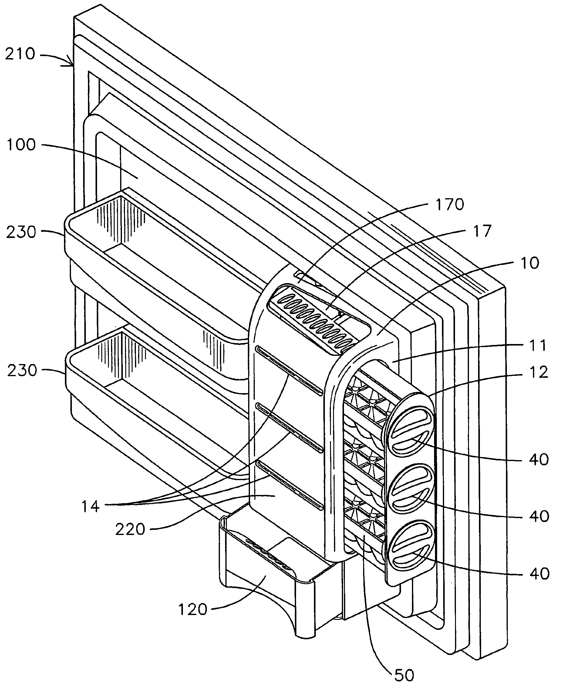
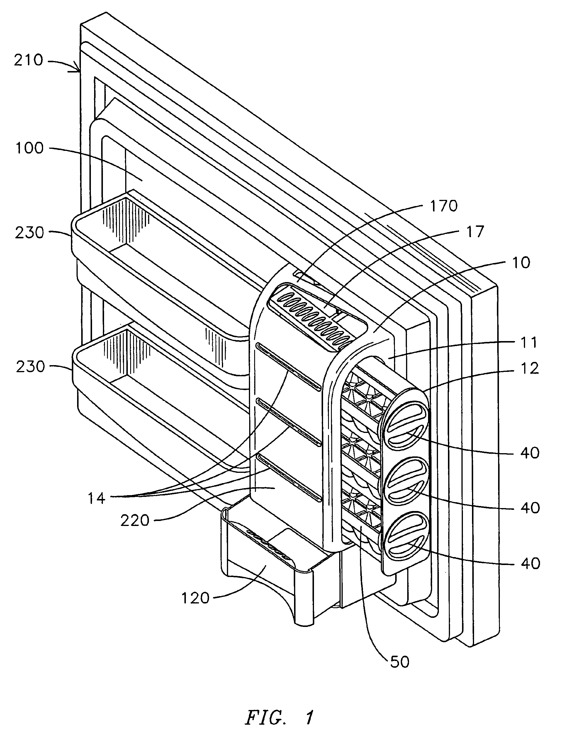
[0034]Case 10 is provided on one side with a side opening 11 which receives a magazine 12 (shown in FIG. 1 as not fully inserted into case 10). The magazine holds ice-cube trays 50 and is provided with one or more ice-cube extraction knobs 40 on one side, which upon being turned in a certain direction (e.g., clockwise) to a certain angle cause a torsional force (e.g., a twisting torque) to be applied to a respective ice-cube tray 50, which in turn causes ice cube removal from the ice-cube tray due to a momentary mechanical distortion (e.g., twisting) imparted to the tray. To enhance the twisting effect, the torque may be distributed by means of suitably positioned limits at or near diagonally opposite corners of the tray.
[0035]By means of ramps, such as in the form of vanes 21 (FIG. 4), the ice cubes are directed to an ice-cube passage to eventually reach the collecting drawer 120. Case 10 may be optionally provided with a series of air inlet slits 14 which may allow for even a fast...
first embodiment
[0073]The rack 60 shown in FIG. 10 may be attached to the liner 100 of the freezer door 220 in essentially the same way as in the first embodiment, and will not be described again.
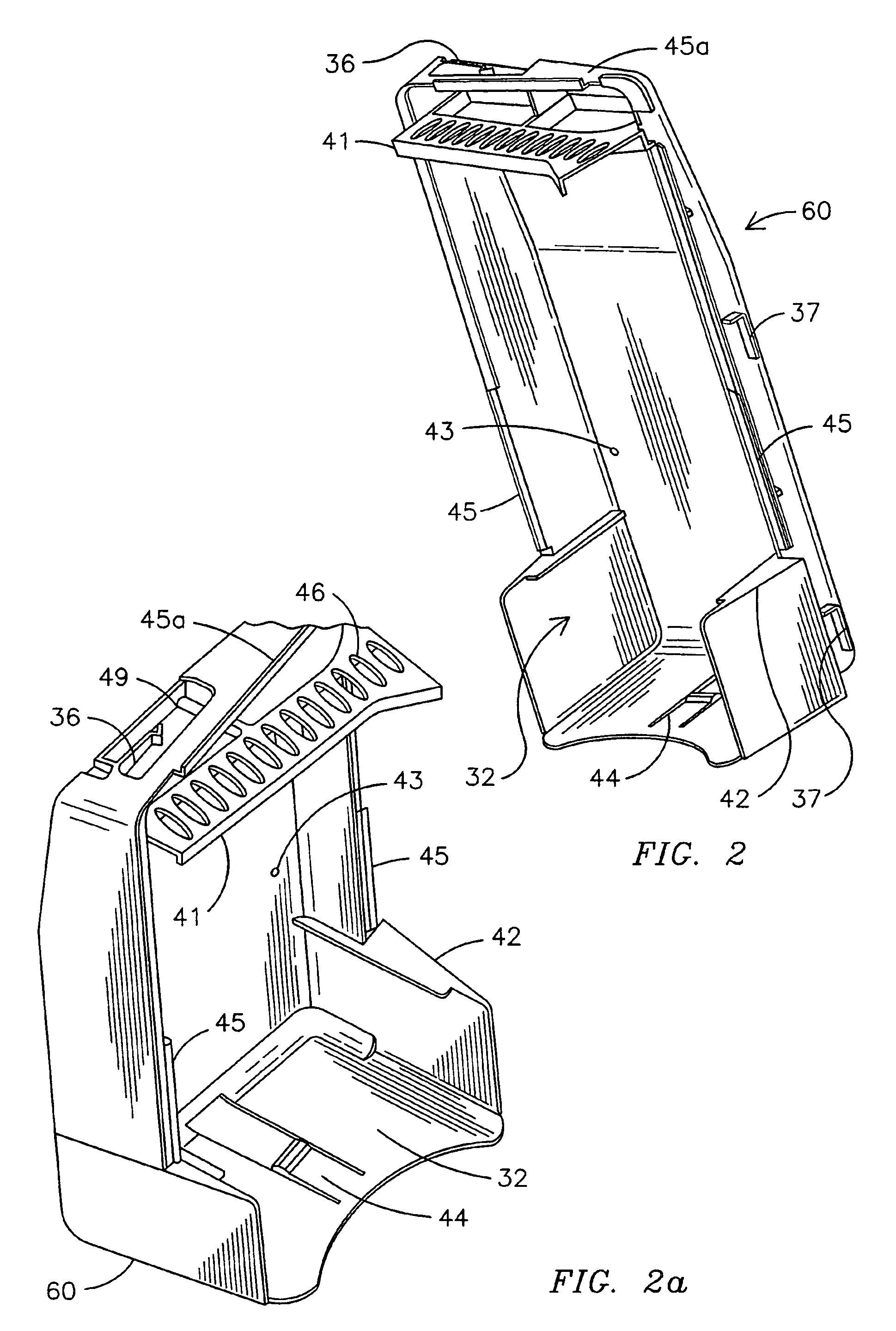
[0074]At the top of the case there is case lock 35, which may have a wedge-shaped head and its body may be arranged as a springboard, the thinnest part of the wedge-shaped head is introduced under the top of case 10, resulting in the deformation of case lock 35 downwards along the vertical axis. Once the deformation force stops acting, the case lock 35 secures the case 10. To lower down case 10 the head of lock 35 should be pressed down to deform the lock and release the case.
[0075]On the middle section of the rack we find the ramp-shaped vanes 30, which in this embodiment may be slotted to enable incremental air flow when assembled in the body of the rack 60. The vanes 30 together with the back wall of the rack 60 forms an ice cube passage 34, through which ice cubes can pass when expelled from the ice-cu...
PUM
 Abstract
Description
Claims
Application Information
 - R&D
- Intellectual Property
- Life Sciences
- Materials
- Tech Scout
- Unparalleled Data Quality
- Higher Quality Content
- 60% Fewer Hallucinations
Browse by: Latest US Patents, China's latest patents, Technical Efficacy Thesaurus, Application Domain, Technology Topic, Popular Technical Reports.
© 2025 PatSnap. All rights reserved.Legal|Privacy policy|Modern Slavery Act Transparency Statement|Sitemap|About US| Contact US: help@patsnap.com


