Device and method for spacing and bracing framing components

Inactive Publication Date: 2007-05-08
SACKETT GERALD L
View PDF12 Cites 31 Cited by
  • Summary
  • Abstract
  • Description
  • Claims
  • Application Information

AI Technical Summary

Benefits of technology

[0016]The method of using the device of the invention comprises the steps of affixing the aforementioned spacing and bracing device upon one edge of the first framing component by placing an edge of the first component into the channel formed by the side webs; engaging the pivotable connection means to produce a pivot point between the pivot tongue and the first component; positioning the first and second framing components into their approximate final positions relative to each other; bending the upper web at the hinge means by raising the free tongue away from the edge of the first component until the side webs clear the upper surface of the first component; rotating the device about the pivot point until the side webs point toward the second fram

Problems solved by technology

One of the major disadvantages of the foregoing examples of spacing and bracing devices is that the framers must carry the braces, clips, and other paraphernalia to the point at which they are to be attached to the framing components.
If such braces are attached to the framing components before the components are placed into position, then the braces stick out from the framing components at right angles and complicate handling and moving the components.
While Allen solves the problem of having to store bracing elements at the work site and carry them around, the L-shaped spacing member Allen discloses does not provide sufficient frictional contact

Method used


Image

  • Device and method for spacing and bracing framing components
  • Device and method for spacing and bracing framing components
  • Device and method for spacing and bracing framing components

Examples


Embodiment Construction

[0027]The inventive concepts and novel features of the invention are described herein with reference to specific embodiments, which embodiments represent the best mode known to me for making and using the invention. However, it is to be noted that the embodiments as described herein are not meant to limit the scope of the invention but rather are representative of many possible embodiments that incorporate the inventive concepts of my invention.

1. Structural Features

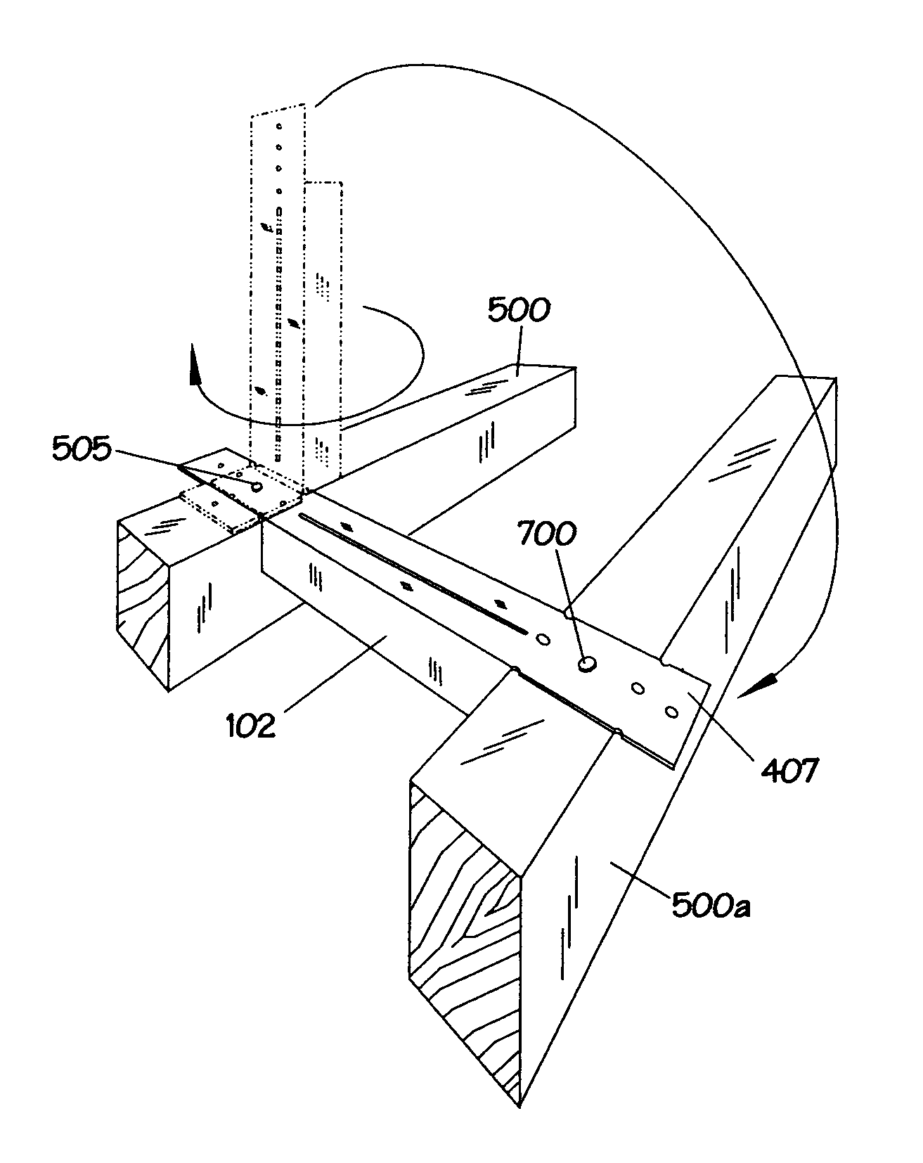
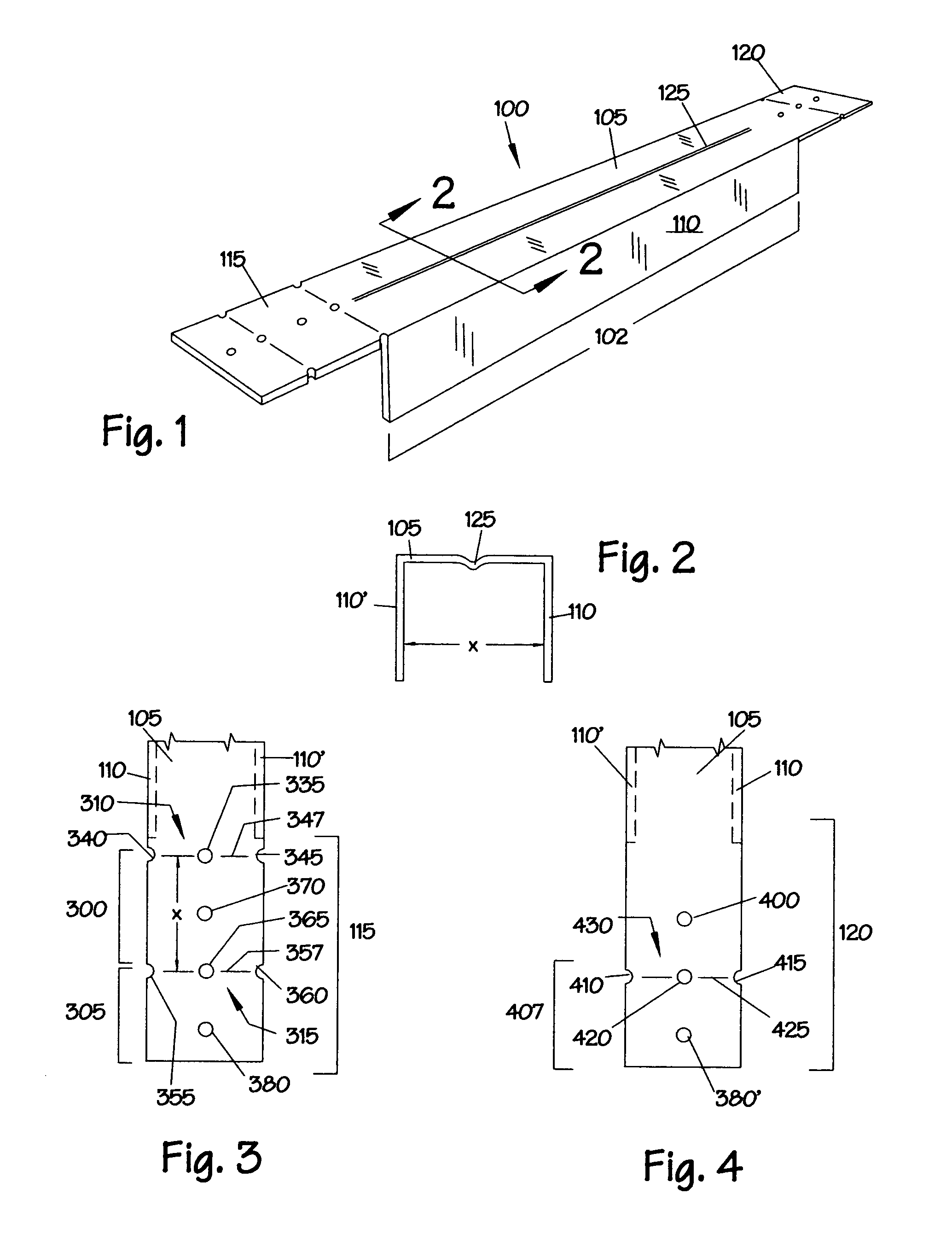
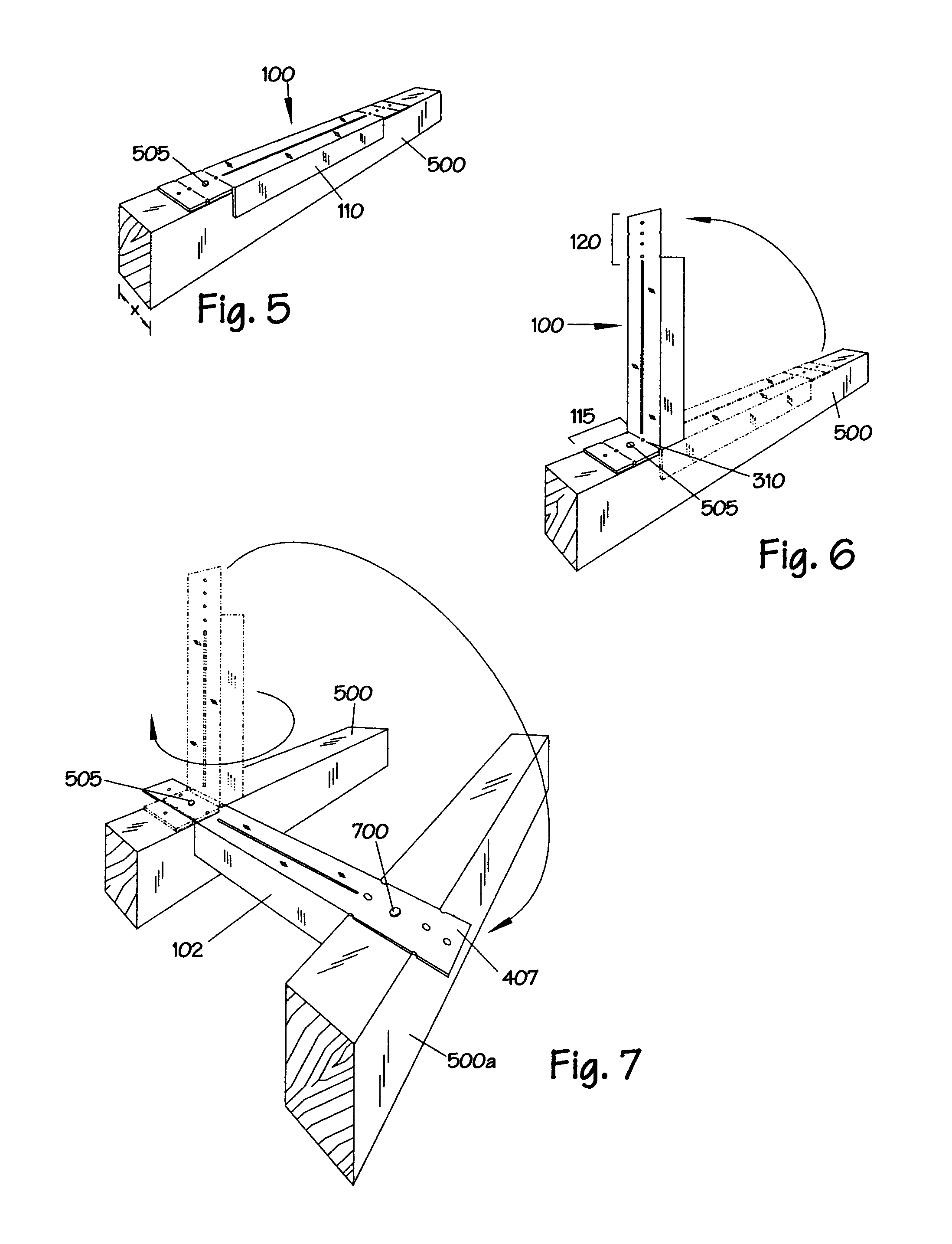
[0028]The structural features of the preferred embodiment of a device 100 for spacing and bracing framing components are shown in FIGS. 1–4. The device comprises an elongate spacing member 102 having two ends. The spacing member in cross-section comprises an upper web 105 and two side webs 110 and 110′ depending approximately orthogonally from the upper web. Each side web forms an opposing side of a U-shaped channel. The distance between the inner sides of the channel is depicted in FIG. 2 and referred to herein as x, wh...


PUM


Abstract

The present invention is a device and method for simultaneously spacing and bracing adjacent framing components. The disclosed device is an elongate U-shaped spacing member having a pivot tongue extending from one end of the spacing member and a free tongue extending from the other end. The pivot tongue incorporates a pivot plate with a pivotable connection means, and a hinge. The free tongue incorporates an attachment means. Optionally, both or either tongue may incorporate a locking tab. The steps of the disclosed method of the invention include affixing the device to the edge of an incoming framing component; pivotally connecting the pivot tongue to the incoming framing component; positioning the components into their approximate positions relative to one another; lifting the free tongue away from the incoming framing component; rotating the device so that the sides of the spacing member face a fastened component; lowering the free tongue until it contacts the fastened component; finally adjusting the positions of the framing components; engaging the attachment means; tightening the pivotable connection; and, optionally, engaging the locking tabs.

Description

BACKGROUND OF THE INVENTION[0001]1. Field of the Invention[0002]The invention relates to devices and methods for spacing and bracing framing components during the framing of buildings and other structures.[0003]2. Statement of the Problems Solved by the Invention[0004]Typically, buildings are constructed by initially assembling a frame from a plurality of framing components. The elemental framing components that constitute a building frame are typically elongated pieces of wood or metal. Examples of such basic framing components include studs, rafters, and joists. Other types of framing components include metal or wood “I”-beams and complex components, such as trusses, which are often preassembled from basic wood or metal elements. Once the frame is complete, internal and external sheathing is attached, thereby adding to the strength and rigidity of the structure, as well as providing the flat surfaces that constitute interior and exterior walls, floors, ceilings and roofs.[0005]Des...

Claims


Application Information

Patent Timeline
IPC IPC(8): E04C3/02E04C3/30E04H12/00
CPCE04C3/02E04B2001/2696E04C2003/026
Inventor SACKETT, GERALD L.
Owner SACKETT GERALD L
Why Eureka
Try Eureka