Dual-direction pulley system

a pulley system and pulley technology, applied in the field of pulley systems, can solve the problems of large benches and occupied space when lying down

Active Publication Date: 2007-05-29
NAUTILUS INC
View PDF167 Cites 93 Cited by
  • Summary
  • Abstract
  • Description
  • Claims
  • Application Information

AI Technical Summary

Benefits of technology

[0010]Accordingly, it is a primary object of the present invention to provide a dual-direction pulley system that provides resistance to movement of an actuator in a first direction and provides resistance to movement of the actuator in a second direction opposite to the first direction.

Problems solved by technology

Lying down also takes up quite a bit of space compared to sitting, and thus these benches are quite large.

Method used


Image

  • Dual-direction pulley system
  • Dual-direction pulley system
  • Dual-direction pulley system

Examples


Embodiment Construction

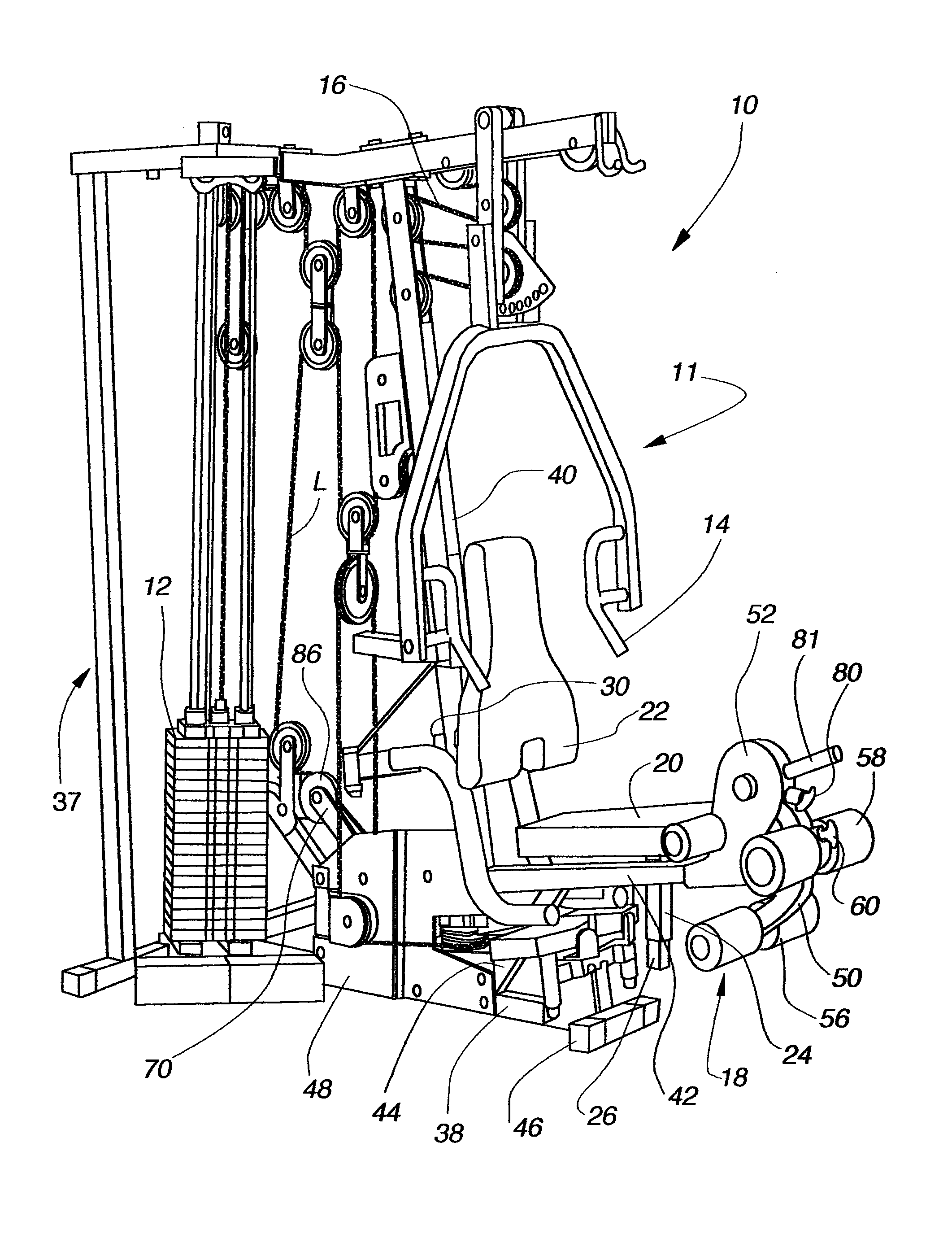
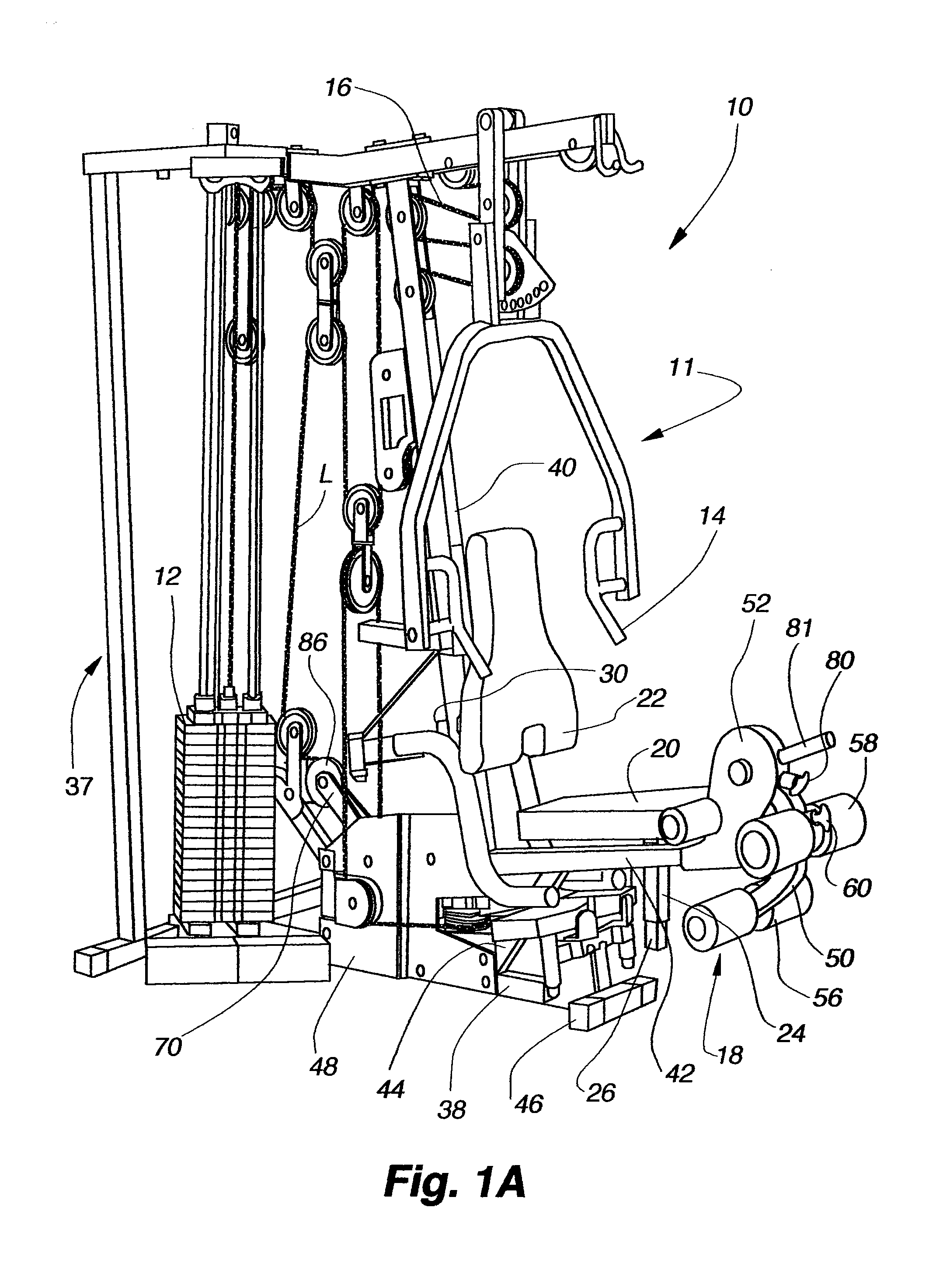
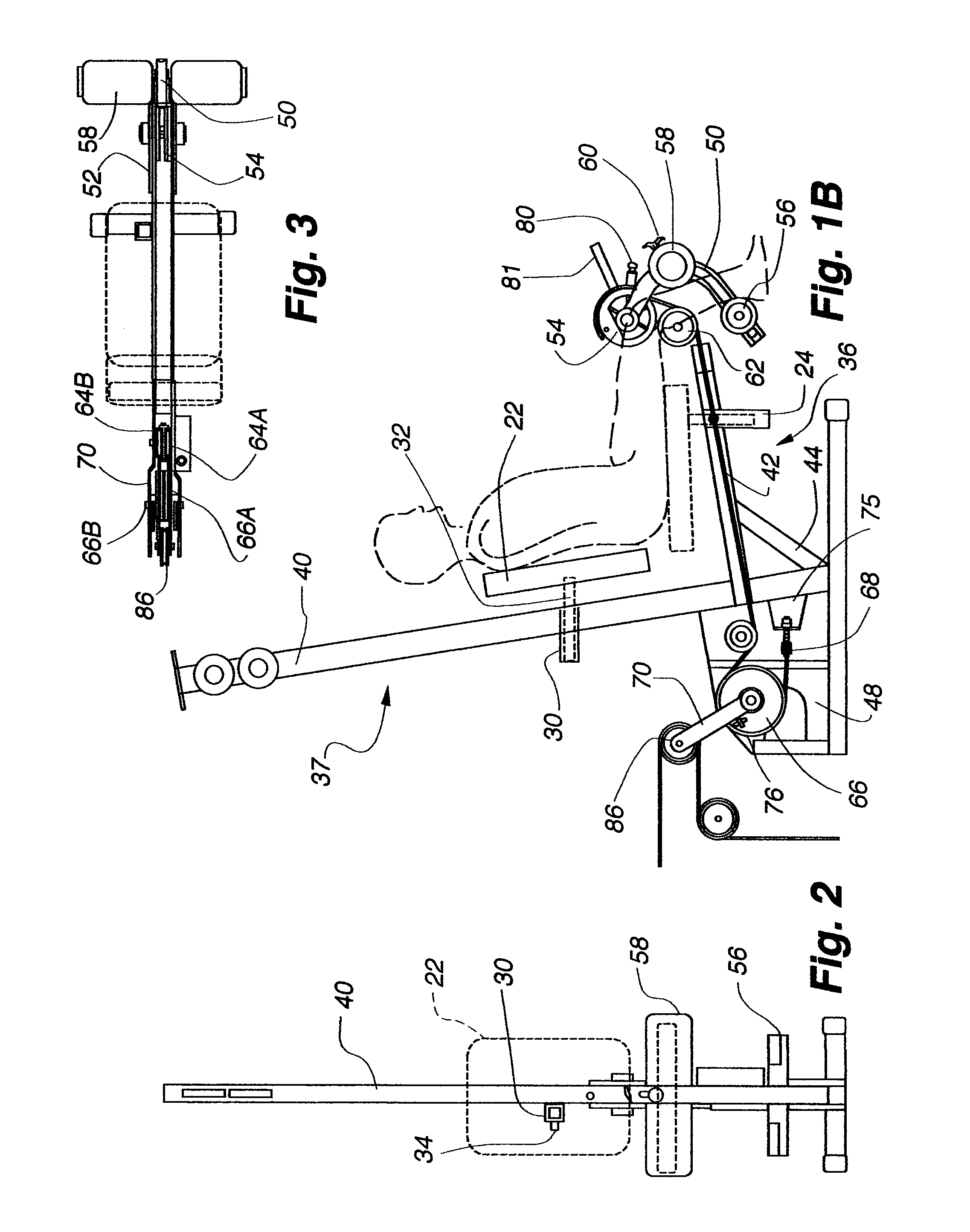
[0024]The present inventive dual-direction pulley system is embodied in a seated leg curl / extension exercise machine, either independent from or designed as a portion of a multi-station weight machine. One such multi-station weight machine is the NS-700 by Nautilus, Inc. It is contemplated that this dual-direction pulley system can be embodied in other types of exercise equipment for the same or different exercises, or in load-transfer structures where dual-direction load transfers are required.

[0025]FIG. 1A shows a multi-station weight machine 10 that incorporates the dual-direction pulley system 5 of the present invention. The weight machine 10 includes a weight stack 12 for providing resistance to various movements for exercises performed at the weight machine stations. In the embodiment shown in FIG. 1A, the weight machine 10 includes a chest exercise station 11 with handles 14 for performing chest and arm exercises. Load cables 16 transmit the resistance of the weight stack 12 ...


PUM


Abstract

A dual-direction pulley system is disclosed in conjunction with an exercise machine. The pulley system provides resistance to a pivotally mounted actuator lever when the lever is rotated clockwise and when the lever is rotated counterclockwise. In a preferred embodiment the dual-direction pulley system provides resistance for a seated leg curl / extension exercise machine such that a user can perform leg curls and leg extensions from a single seated position.

Description

[0001]This application claims the benefit of related U.S. Provisional Application Ser. No. 60 / 402,327, filed on Aug. 8, 2002. U.S. Provisional Application Ser. No. 60 / 402,327 is hereby incorporated by reference.FIELD OF INVENTION[0002]This invention relates to pulley systems allowing resisted motion in two directions, for example in weight stack applications. More particularly, this invention is a dual-direction pulley system for use in a seated leg curl / leg extension station on a multi-station weight stack.BACKGROUND[0003]Leg extension and leg curl exercises typically have to be performed on separate machines due to the opposite motions required for each exercise. In a leg extension, the user extends his leg from a 90 degree position to a straight position. This exercise uses the muscles in the top, front (quadriceps) of the leg. In a leg curl, the user contracts his leg from a straight position to a 90 degree position. This exercise uses the muscles in the top, back (hamstring) of...

Claims


Application Information

Patent Timeline
Patent Type & Authority Patents(United States)
IPC IPC(8): A63B23/04A63B21/062A63B21/00
CPCA63B21/1469A63B21/1492A63B21/159A63B23/03525A63B23/0494A63B21/154A63B21/062A63B2208/0233A63B21/0628A63B21/4035A63B21/4047
Inventor GOLESH, ERIC D.
Owner NAUTILUS INC
Why Eureka
Try Eureka