Occlusive cinching devices and methods of use

a technology of occlusion and orifice, which is applied in the field of occlusion cinching devices and methods of use, can solve the problems of permanent and irreversible occlusion of parent arteries, disadvantages of injection of these types of embolic materials, and trauma to patients, so as to prevent the egress of embolic materials

Active Publication Date: 2007-06-12
STRYKER EURO OPERATIONS HLDG LLC +1
View PDF50 Cites 75 Cited by
  • Summary
  • Abstract
  • Description
  • Claims
  • Application Information

AI Technical Summary

Benefits of technology

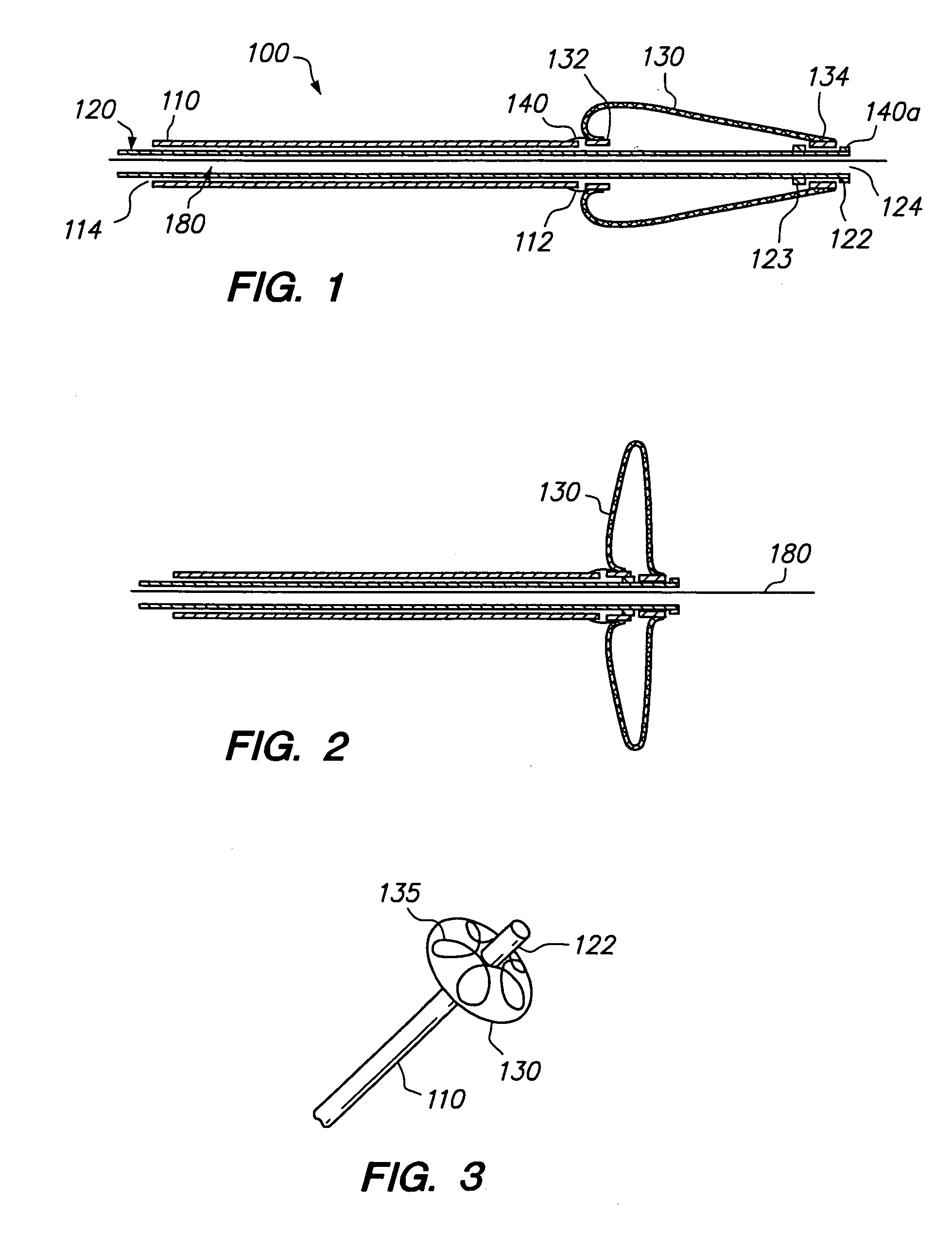
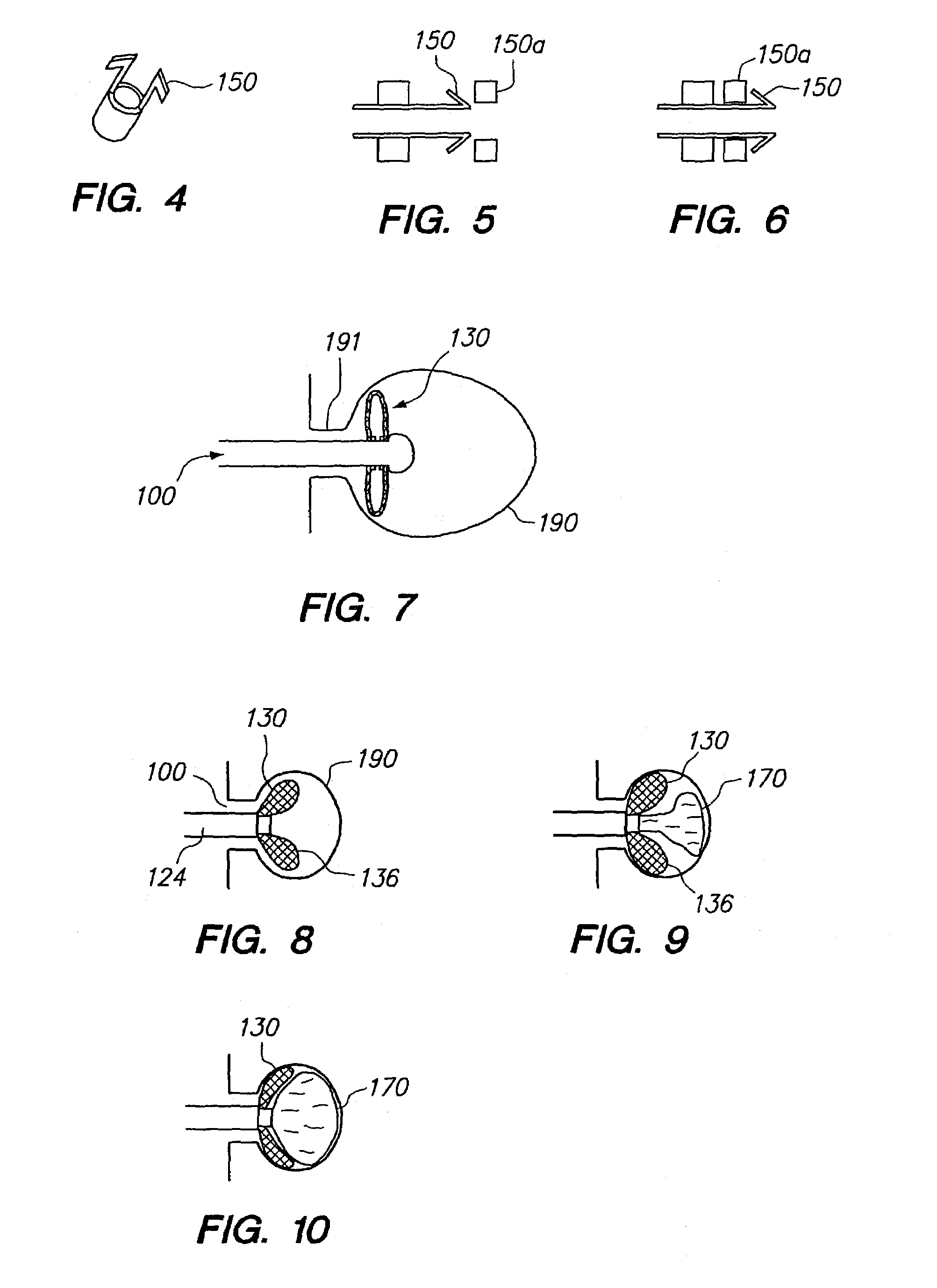
[0010]Methods and devices for blocking orifices and occluding cavities within a patient are provided. The device comprises first and second tubular members attached at their distal ends to a collapsible sealing element. The device can be placed through an orifice and the collapsible sealing element can be collapsed to seal the orifice. An embolic may be introduced distal to the sealing element to occlude a cavity. The device may incorporate a locking mechani...

Problems solved by technology

Also, the patient undergoes a great deal of trauma in the area of the aneurysm by virtue of the fact that the surgeon must sever various tissues in order to reach the aneurysm.
The injection of these types of embolic materials suffer from disadvantages, most of which are associated with migration of the embolic material out of the aneurysm into the parent artery.
This can cause permanent and irreversible occlusion of the parent artery.
Further, it is, at times, difficult to gauge exactly how full the sac of the aneurysm is when detachable coils are being injected.
Therefore, there is a risk of overfilling the aneurysm in which case the detachable coils also spill out into the parent artery.
Another disadvantage of detachable coils involves coil compaction over time.
Continued hemodynamic forces from the circulat...

Method used


Image

  • Occlusive cinching devices and methods of use
  • Occlusive cinching devices and methods of use
  • Occlusive cinching devices and methods of use

Examples


Embodiment Construction

[0023]Before the present invention is described in detail, it is to be understood that this invention is not limited to the particular methodology, devices or apparatuses described, as such methods, devices or apparatuses can, of course, vary. It is also to be understood that the terminology used herein is for the purpose of describing particular embodiments only, and is not intended to limit the scope of the present invention.

[0024]Use of the singular forms “a,”“an,” and “the” include plural references unless the context clearly dictates otherwise. Thus, for example, reference to “an embolic” includes a plurality of embolics, reference to “a locking mechanism” includes a plurality of such mechanisms, and the like.

[0025]Terms such as “connected,”“attached,”“linked,” and “conjugated” are used interchangeably herein and encompass direct as well as indirect connection, attachment, linkage or conjugation unless the context clearly dictates otherwise.

[0026]Unless defined otherwise or the...


PUM


Abstract

Methods and devices for blocking orifices and occluding cavities within a patient are provided. The device in one variation comprises first and second tubular members attached to a collapsible sealing element. The device can be placed through an orifice and the collapsible sealing element can be collapsed to seal the orifice. An embolic may be introduced distal to the sealing element to occlude a cavity. The device may incorporate a locking mechanism which can be engaged to lock the sealing element into the collapsed position. The device may incorporate a valve to prevent flow through the tubular members, for example to prevent egress of the embolic from a cavity. The device can be detached to provide a permanent seal of the orifice, and can retain the embolic within the cavity. The device may be used in conjunction with a stent or other retention device to assist the sealing element in maintaining the seal.

Description

TECHNICAL FIELD[0001]This invention relates to methods and devices for blocking orifices and occluding cavities within a patient.BACKGROUND OF THE INVENTION[0002]The present invention deals with a system for treating an aneurysm. More specifically, the present invention deals with a removable occlusion system deployed in the vasculature containing the aneurysm.[0003]Several methods of treating aneurysms have been attempted, with varying degrees of success. For example, open craniotomy is a procedure by which an aneurysm is located, and treated, extravascularly. This type of procedure has significant disadvantages. For example, the patient undergoing open craniotomy must undergo general anesthesia. Also, the patient undergoes a great deal of trauma in the area of the aneurysm by virtue of the fact that the surgeon must sever various tissues in order to reach the aneurysm. In treating cerebral aneurysms extravascularly, for instances, the surgeon must typically remove a portion of the...

Claims


Application Information

Patent Timeline
IPC IPC(8): A61B17/08A61B17/12
CPCA61B17/12022A61B17/12113A61B17/12172A61B17/1219A61B17/12186A61B2017/12063A61B2017/1205
Inventor TRAN, TRINGUYEN, KIMHO, HANHDOAN, MYMURPHY, RICHARDWALLACE, MICHAEL P.TEOH, CLIFFORD
Owner STRYKER EURO OPERATIONS HLDG LLC
Why Eureka
Try Eureka