Electrical zero insertion force connector

a zero-inserting force, connector technology, applied in the direction of coupling contact member, electrical apparatus, coupling/disengagement parts, etc., can solve the problems of high assembly cost, high assembly cost, and high electrically connecting parts

Inactive Publication Date: 2007-06-19
KOSTAL KONTAKT SYST
View PDF18 Cites 17 Cited by
  • Summary
  • Abstract
  • Description
  • Claims
  • Application Information

AI Technical Summary

Benefits of technology

[0016]In joining the housing parts to the second connector part, first the plug is inserted without force into the contact segments of the contact sleeve. Further motion of the plug detaches the connection between the two housing parts and causes the housing parts to move relative to one another, and at the same time the clamping sleeve moves relative to the contact sleeve body into the activation position. It is advantageous as the sleeve contact is activated by being joined to the counter-contact (i.e., the plug).

Problems solved by technology

As such, considerable force is required for electrically connecting the parts together.
This is a problem where space is at a premium or is relatively unaccessible.
A problem is that the activation element can move, prior to the parts being mechanically connected together, in response to elements of the first part moving against one another and activating the activation element.
This results in higher assembly costs as the activation element has to be moved out of the activated position for the parts to be properly assembled together.

Method used


Image

  • Electrical zero insertion force connector
  • Electrical zero insertion force connector
  • Electrical zero insertion force connector

Examples


Embodiment Construction

)

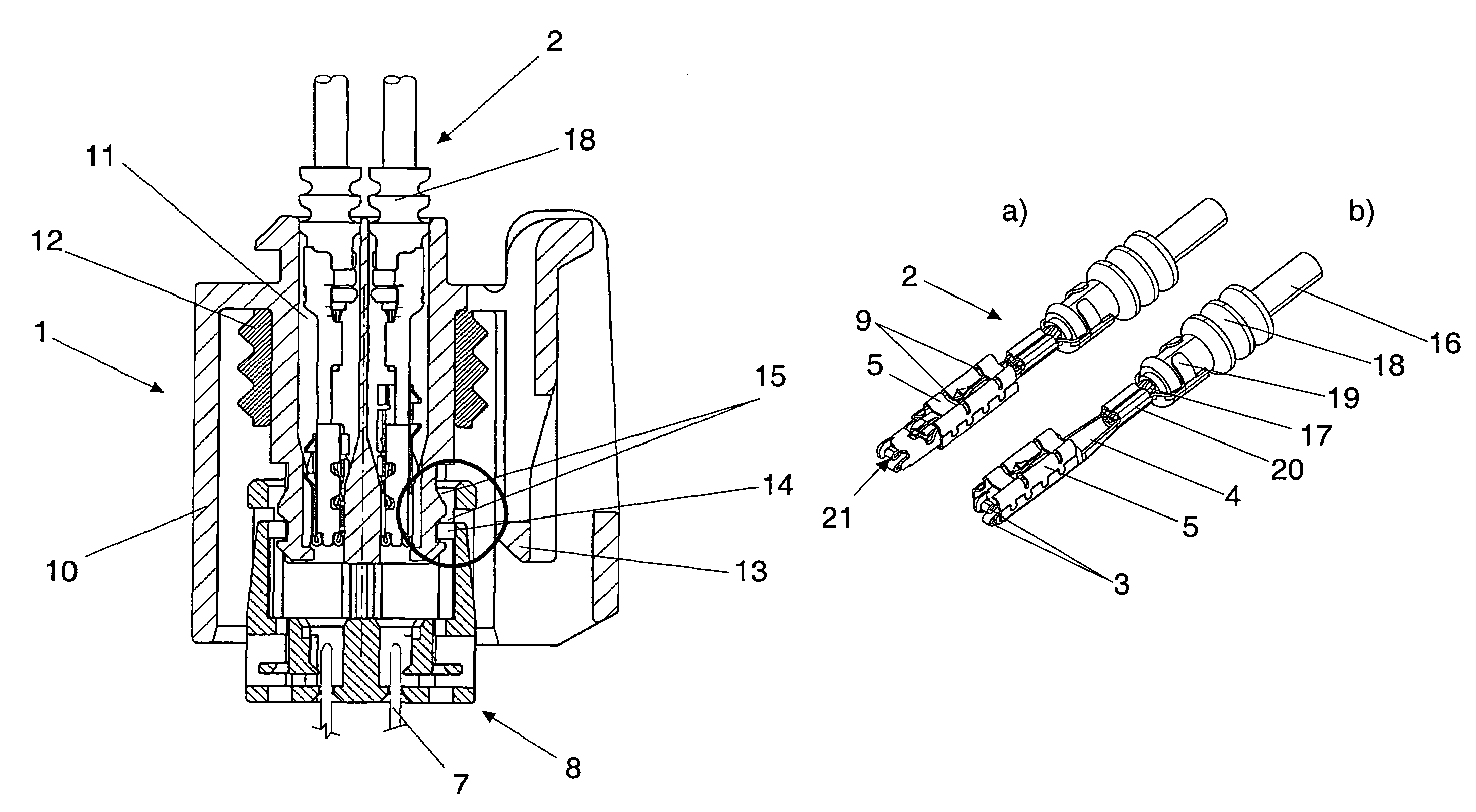
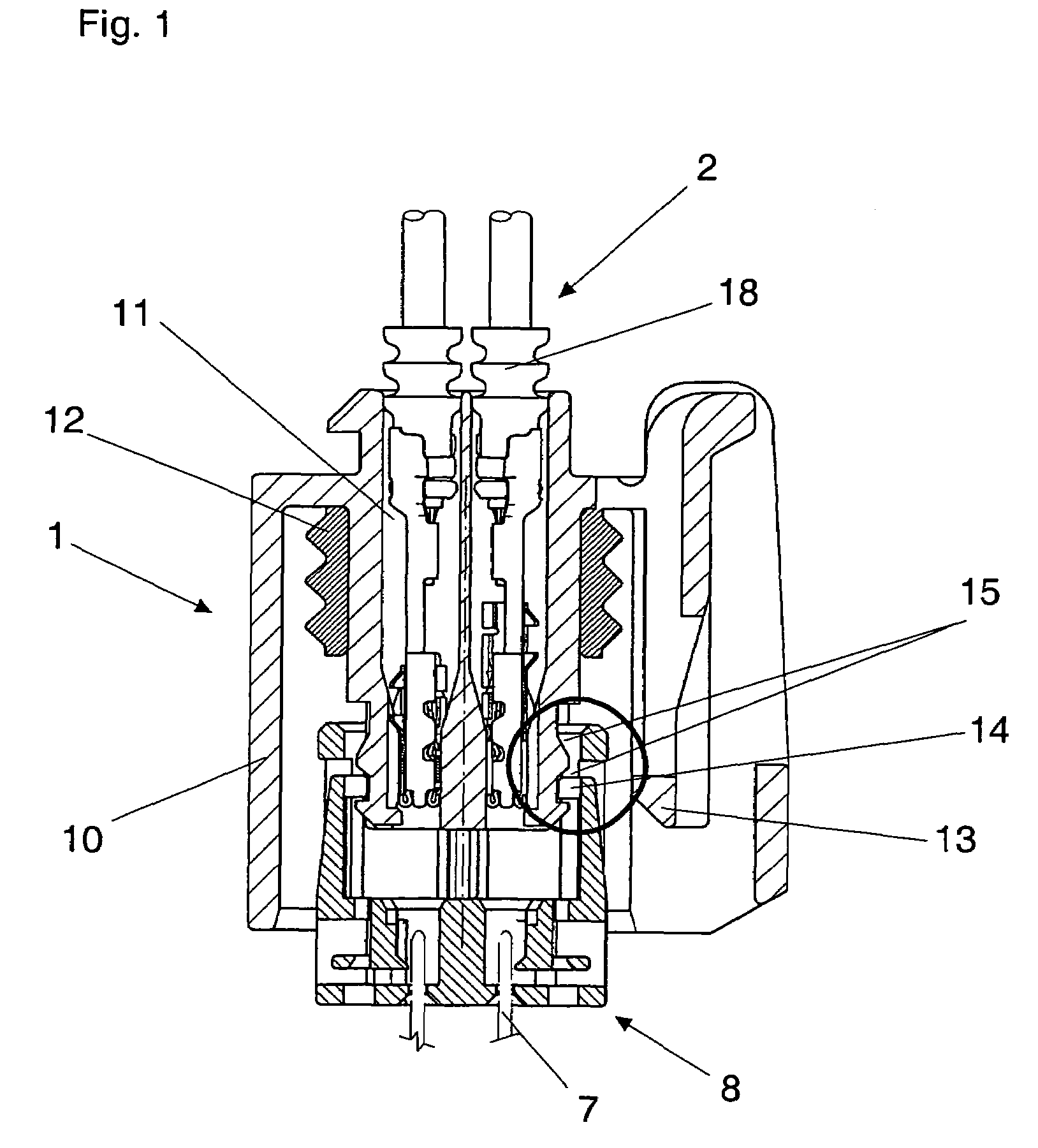
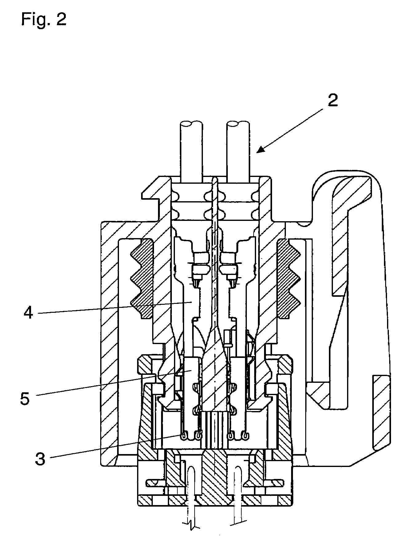
[0024]FIGS. 1, 2, and 3 illustrate respective sectional views of a first plug-and-socket connector part of an electrical zero force insertion connector in various joined stages. FIG. 4 illustrates a sectional view of the first connector part and a second connector part 6 mechanically and electrically interconnected to form the electrical zero force insertion connector.

[0025]The first connector part includes a first housing 1 and a second housing 8. First housing 1 and second housing 8 are independent housing parts which connect together to form the first connector part. Second housing 8 assumes either a pre-locked position or a final locked position relative to first housing 1 when the first and second housings are connected. That is, second housing 8 is movably connected to first housing 1 between the pre-locked position and the final locked position. FIGS. 1, 2, and 3 illustrate second housing 8 in the pre-locked position. FIG. 4 illustrates second housing 8 in the final locked p...


PUM


Abstract

An electrical zero insertion force connector includes a first part having two housings, a second part having a plug, and a sleeve contact having contact segments with a gap. A clamp movably connects to the sleeve contact. The second housing movably connects to the first housing. The sleeve contact extends into the first housing such that the clamp engages the first housing and the contact segments engage the second housing. The second part connects to the first housing such that the parts connect together with the plug inserted into the gap. Upon connecting to the first housing, the second part disengages the second housing from the first housing and moves the second housing toward the first housing such that the sleeve contact moves with the second housing away from the clamp until the clamp moves over the contact segments and presses the contact segments onto the plug.

Description

CROSS-REFERENCE TO RELATED APPLICATIONS[0001]This application claims foreign priority benefits under 35 U.S.C. §119(a)-(d) to DE 10 2005 040 952.0, filed Aug. 30, 2005, which is hereby incorporated by reference in its entirety.BACKGROUND OF THE INVENTION[0002]1. Field of the Invention[0003]The present invention relates to an electrical zero insertion force connector having first and second connector parts in which the first part includes a housing having a receptacle with a sleeve contact contained therein, the sleeve contact having contact segments and a clamping sleeve movable relative to the contact segments, and in which the second part has a plug pin which inserts into the contact segments to electrically connect the parts together upon the parts being mechanically connected together.[0004]2. Background Art[0005]Plug-and-socket connectors are used to electrically connect individual modules, flexible foils, printed circuit boards, etc., together. For example, plug-and-socket con...

Claims


Application Information

Patent Timeline
Patent Type & Authority Patents(United States)
IPC IPC(8): H01R13/15
CPCH01R13/18H01R13/193H01R13/4365
Inventor MOHS, WOLFGANGHERINGHAUS, WILFRIED
Owner KOSTAL KONTAKT SYST
Why Eureka
Try Eureka