

Cable connector assembly with unitary latch
a technology of connector assembly and latch, applied in the direction of electrical apparatus, connection, coupling device connection, etc., to achieve the effect of improving the latch
- Summary
- Abstract
- Description
- Claims
- Application Information
AI Technical Summary
Benefits of technology
Problems solved by technology
Method used
Image

Examples
Embodiment Construction
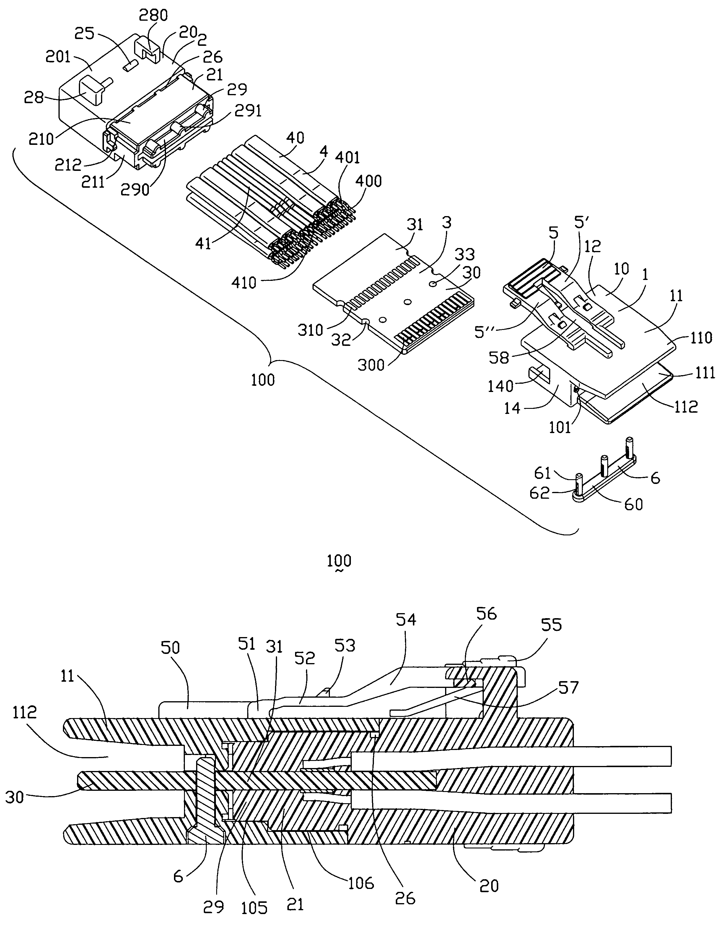
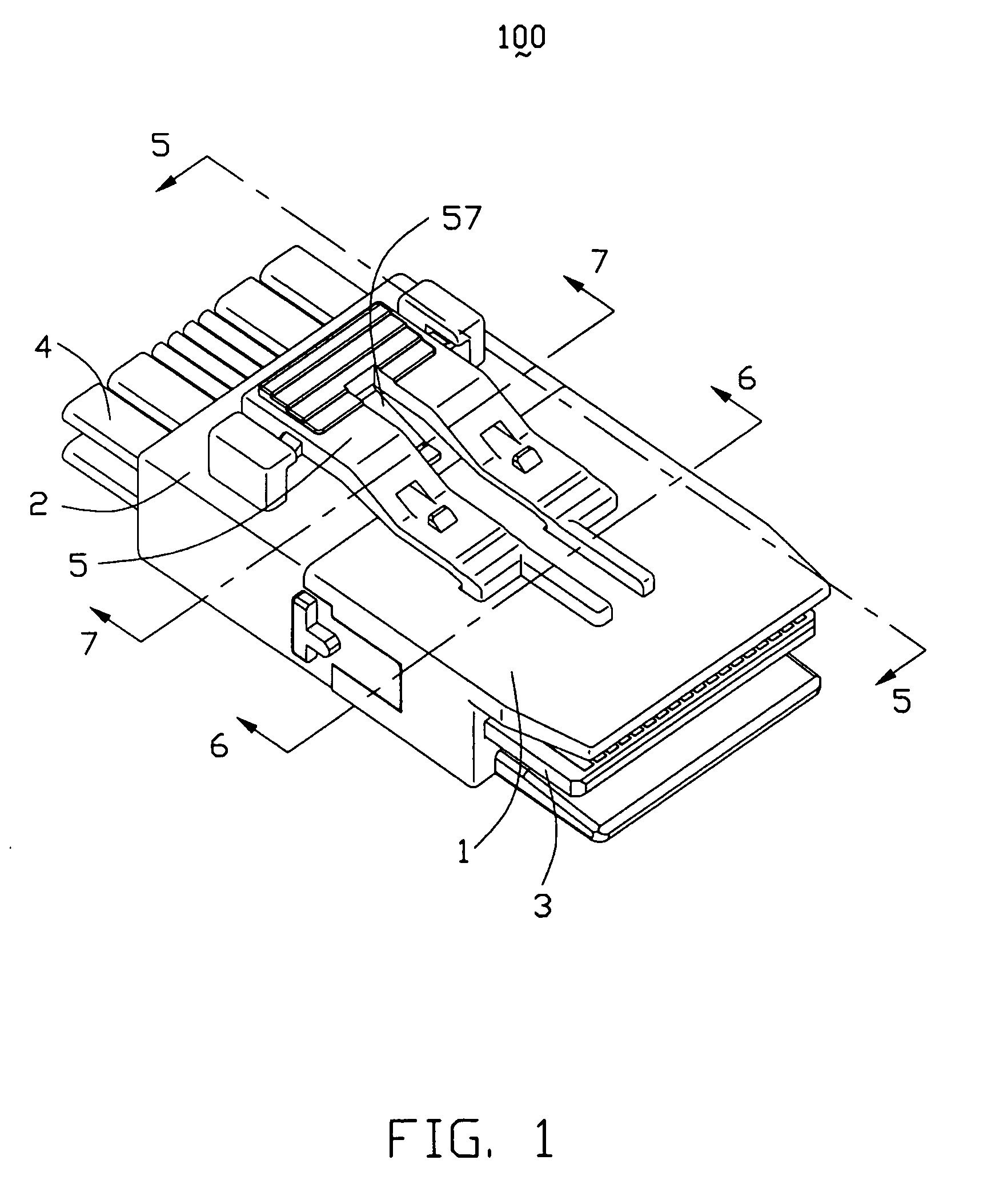
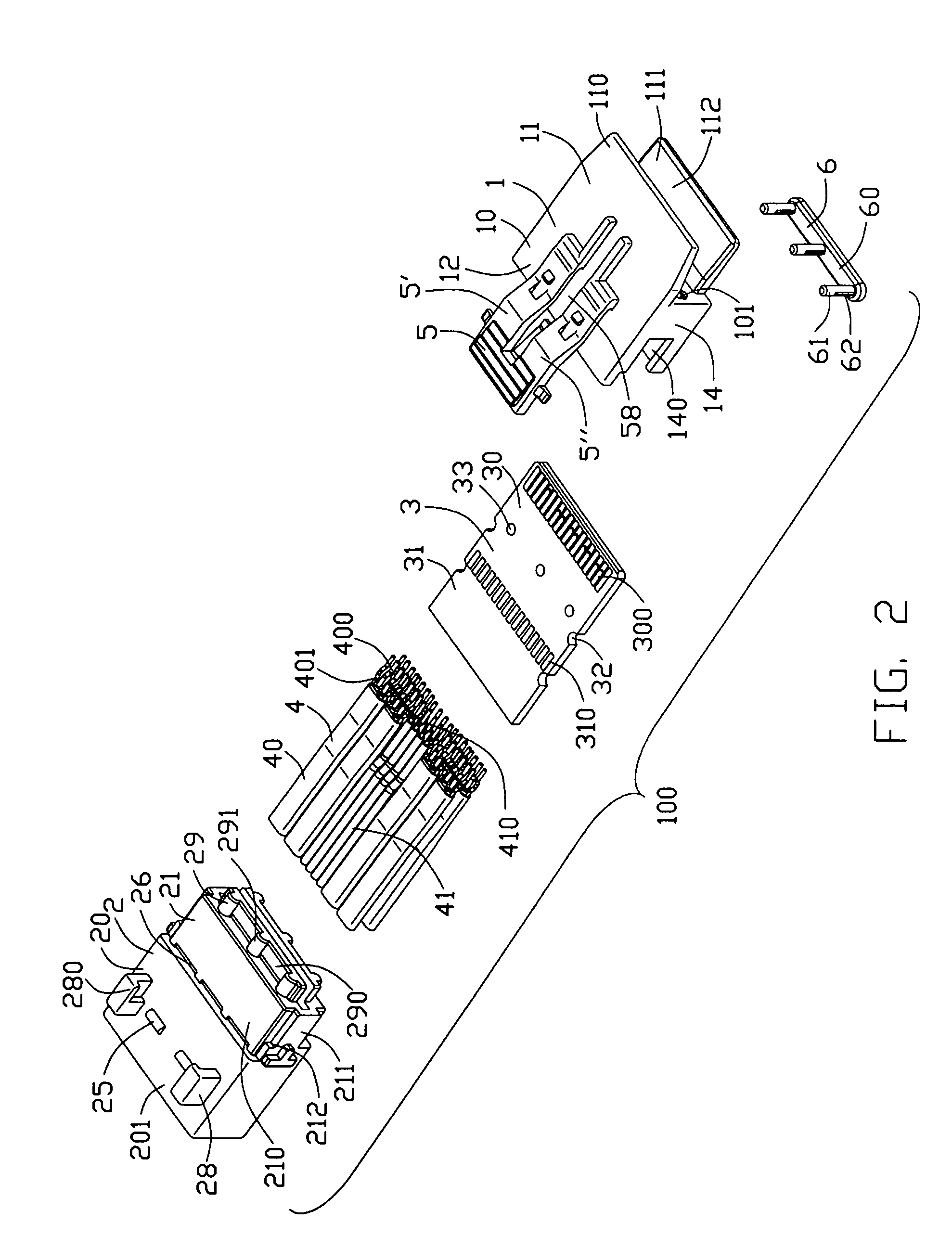
[0019]Referring to FIGS. 1 to 4, a cable connector assembly 100 in accordance with the present invention comprises a connector housing (not labeled) defining a mating direction, and including a front first housing piece 1 and a rear second housing piece 2, a printed circuit board 3 assembled to the connector housing, a plurality of cables 4 electrically connected to the printed circuit board 3, a pin member 6 assembled to the connector housing for holding the printed circuit board 3 with the connector housing reliably, and a resilient latch 5 unitarily molded with the connector housing for attaching the cable connector assembly 100 with a complementary connector (not shown).
[0020]Referring to FIGS. 1–7, the first housing piece 1 is made of insulative material with enough rigidity. The first housing piece 1 comprises a rectangular body portion 10 defining a central receiving slot 101 therethrough, and a pair of tongue sections 110, 111 opposite to each other and respectively extendin...
PUM
 Abstract
Description
Claims
Application Information