
Crankshaft for V-type six-cylinder engine

a crankshaft and cylinder head technology, applied in the direction of crankshafts, machines/engines, mechanical equipment, etc., can solve the problem that the unbalance couple generated therein cannot be reduced to a sufficient degree, and achieve the effect of reducing the generated unbalance coupl

Inactive Publication Date: 2007-06-26
TOYOTA IND CORP
View PDF13 Cites 16 Cited by
  • Summary
  • Abstract
  • Description
  • Claims
  • Application Information

AI Technical Summary

Benefits of technology

[0009]The present invention has been made with a view toward solving the above problem in the prior art. It is therefore an object of the present invention to provide a crankshaft for a V-type six-cylinder engine, which is capable of reducing the generated unbalance couple to a sufficient degree.

Problems solved by technology

Conventional crankshafts have a problem in that the unbalance couple generated therein cannot be reduced to a sufficient degree.

Method used


Image

  • Crankshaft for V-type six-cylinder engine
  • Crankshaft for V-type six-cylinder engine
  • Crankshaft for V-type six-cylinder engine

Examples


embodiment 1

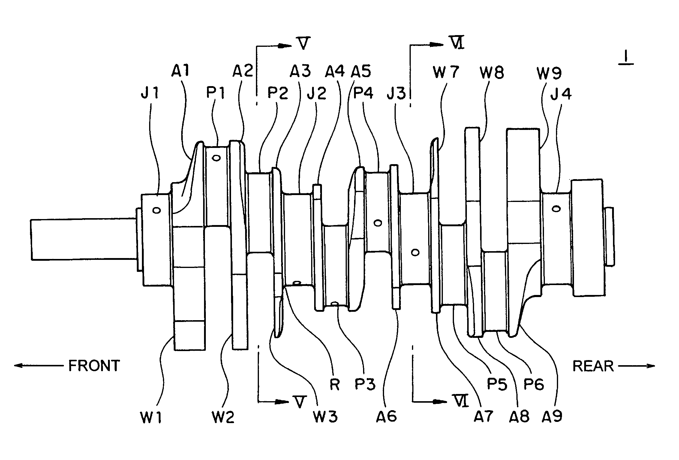
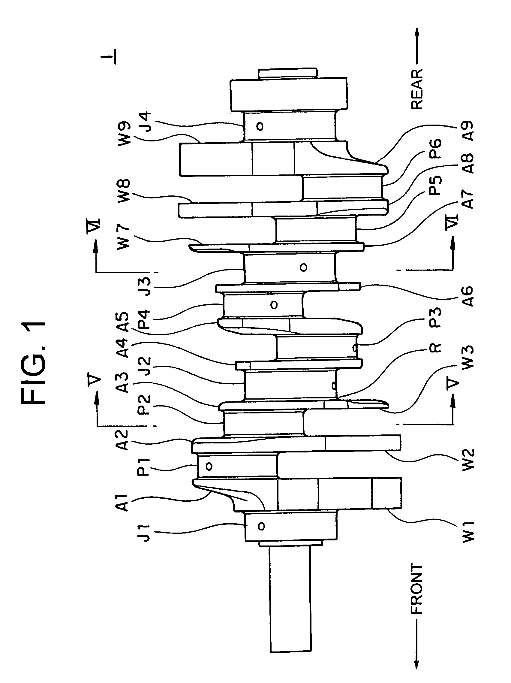
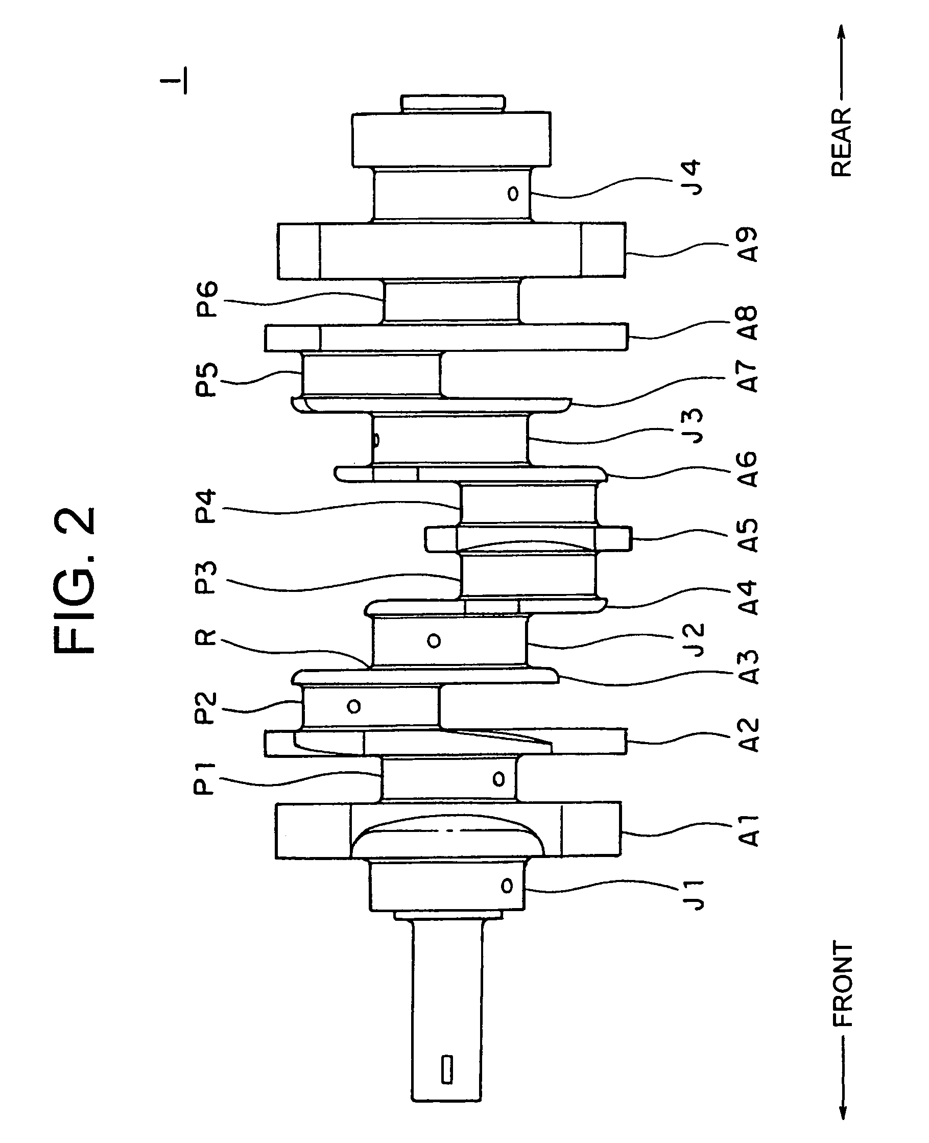
[0038]FIGS. 1 through 3 show a crankshaft 1 according to Embodiment 1 of the present invention. FIGS. 1 through 3 are a right-hand side view, a plan view, and a perspective view, respectively, of the crankshaft 1.

[0039]The crankshaft 1 is for use in a V-type six-cylinder diesel engine with a 60° bank angle, and includes four crank journals (first through fourth crank journals) J1 through J4, six crank pins (first through sixth crank pins) P1 through P6, and nine arms (first through ninth arms) A1 through A9.

[0040]The crank journals J1 through J4 have a substantially cylindrical configuration, each including a cylindrical portion inclusive of a portion near an axial center thereof and radiused portions R formed on both end portions thereof so as to be in contact with the arms A1 through A9 for the purpose of avoiding stress concentration. The crank journals J1 through J4, arranged in the stated order and spaced apart from each other, are arranged coaxially. Central axes of the crank ...

embodiment 2

[0085]A crankshaft (FIG. 11) according to Embodiment 2 of the present invention is realized by modifying the crankshaft 1 according to Embodiment 1 of the present invention such that the arm A5 has a counterweight W5.

[0086]As described below, the counterweight W5 is arranged in a direction opposite the crank pins P3 and P4 with respect to the central axis of the crankshaft 1.

[0087]The arm A5 includes the following portions that are to be defined in the same manner as those of the arms A3 and A7: a connecting portion A5a for connecting the crank pins P3 and P4, an outer edge portion A5b surrounding the outer edge of the connecting portion A5a, and the counterweight W5 for achieving a reduction in rotational force of inertia. Of these, as in the arms A3 and A7, the region composed of a combination of the outer edge portion A5b and the counterweight W5 will be referred to as a surplus weight portion X5. The center of gravity of the surplus weight portion X5 will be referred to as the c...


PUM


Abstract

A crankshaft for a V-type six-cylinder engine is equipped with first through sixth crankpins, first through fourth crank journals, and first through ninth arms for connecting the crank pins and the crank journals to each other. Of the first through ninth arms, the third arm and the seventh arm respectively have surplus weight portions (inclusive of counterweights) whose centers of gravity are situated respectively in a direction substantially opposite the first crank pin and the sixth crank pin.

Description

BACKGROUND OF THE INVENTION[0001]1. Field of the Invention[0002]The present invention relates to a crankshaft for a V-type six-cylinder engine.[0003]2. Description of the Related Art[0004]Generally speaking, a crankshaft used in a V-type six-cylinder engine is equipped with six crank pins, four crank journals, and nine arms for connecting the crank pins and the crank journals to each other. Some of these arms are each equipped with a counterweight for reducing the rotational force of inertia generated in each arm and the unbalance couple generated in the crankshaft.[0005]In a conventional crankshaft, the counterweights are situated in a direction completely opposite the crank pins connected to the arms with respect to the central axis of the crankshaft. That is, in the case of an arm to which only one crank pin is connected, the counterweight is situated in a direction completely opposite that crank pin, and in the case of an arm to which two crank pins are connected, the counterwei...

Claims


Application Information

Patent Timeline
Patent Type & Authority Patents(United States)
IPC IPC(8): F16F15/26
CPCF16C3/20F16F15/24F16C3/08F02B75/22F16C2360/22
Inventor NAGIRA, TETSUSHI
Owner TOYOTA IND CORP
Learn More