Plasma display panel

a technology of display panel and plasma, which is applied in the direction of instruments, discharge tubes luminescnet screens, electrodes, etc., can solve the problems of phosphor layer, unsolved problems, and insufficient lifetime, so as to reduce the initial brightness and suppress the variation of brightness

Inactive Publication Date: 2007-07-03
PANASONIC CORP
View PDF3 Cites 50 Cited by
  • Summary
  • Abstract
  • Description
  • Claims
  • Application Information

AI Technical Summary

Benefits of technology

[0050]In view of the above-mentioned problems in the conventional plasma display panels, it is an object of the present invention to provide a plasma display panel which is capable of suppressing variation in a brightness with the lapse of time without reduction in an initial brightness.
[0055]Herein, variation of a brightness with the lapse of time is equivalent to a lifetime of a phosphor layer composed of phosphor which emits a blue light. That is, a phosphor layer having greater variation of a brightness with the lapse of time would have a shorter lifetime, and a phosphor layer having smaller variation of a brightness with the lapse of time would have a longer lifetime.
[0056]In general, an initial brightness collides with variation of a brightness with the lapse of time in a phosphor layer which emits a blue light. That is, a phosphor layer having a higher initial brightness would have greater variation of a brightness with the lapse of time, in other words, would have a shorter lifetime. In contrast, a phosphor layer having a lower initial brightness would have smaller variation of a brightness with the lapse of time, in other words, would have a longer lifetime. Accordingly, it would be possible to control both an initial brightness and variation of a brightness with the lapse of time by mixing at a predetermined ratio first phosphor having a high initial brightness and hence having great variation of a brightness with the lapse of time, and second phosphor having a low initial brightness and hence having small variation of a brightness with the lapse of time.
[0061]According to the results of the experiments having been carried out by the inventor, when the first and second phosphors are mixed to each other for composing a phosphor layer emitting a blue light, it is preferable that a mixture ratio of the first phosphor is in the range of 10 to 90 weight % relative to a weight of the phosphor layer (accordingly, a mixture ratio of the second phosphor is in the range of 10 to 90 weight % relative to a weight of the phosphor layer). By setting a mixture ratio of the first phosphor in the range of 10 to 90 weight %, it would be possible to have a desired initial brightness and variation of brightness with the lapse of time.
[0071]In general, an initial brightness collides with variation of a brightness with the lapse of time in a phosphor layer which emits a blue light. That is, a phosphor layer having a higher initial brightness would have greater variation of a brightness with the lapse of time, in other words, would have a shorter lifetime. In contrast, a phosphor layer having a lower initial brightness would have smaller variation of a brightness with the lapse of time, in other words, would have a longer lifetime. Accordingly, it would be possible to control both an initial brightness and variation of a brightness with the lapse of time by mixing at a predetermined ratio first phosphor having a high initial brightness and hence having great variation of a brightness with the lapse of time, and second phosphor having a low initial brightness and hence having small variation of a brightness with the lapse of time.

Problems solved by technology

Among those three phosphor layers, a phosphor layer which emits a blue light is accompanied with a problem that an initial brightness and a lifetime collide with each other, and this problem remains unsolved.
Specifically, if a phosphor layer emitting a blue light is composed of a material providing a desired initial brightness, the phosphor layer could not have a sufficient lifetime, and in contrast, if a phosphor layer emitting a blue light is composed of a material providing a desired lifetime, the phosphor layer could not have a sufficient initial brightness.
However, the suggested phosphor is accompanied with a problem that it can suppress variation in a brightness wit the lapse of time, but it unavoidably sacrifices an initial brightness.
However, the suggested plasma display panel is accompanied with a problem that a color degree is unavoidably reduced when a blue light is singly emitted.

Method used


Image

  • Plasma display panel
  • Plasma display panel
  • Plasma display panel

Examples


first embodiment

[First Embodiment]

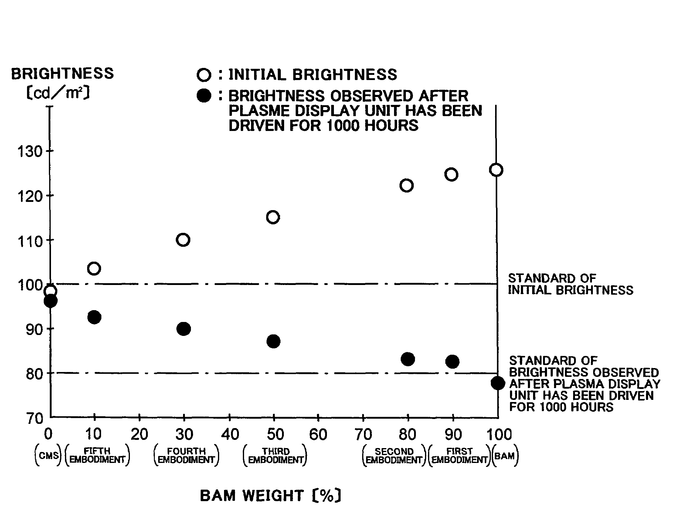
[0085]A phosphor layer emitting a blue light in accordance with the first embodiment of the present invention was comprised of a mixture of first phosphor emitting a blue light, and having a relatively high initial brightness and relatively great variation of a brightness with the lapse of time, and second phosphor emitting a blue light, and having a lower initial brightness than the same of the first phosphor and smaller variation of a brightness with the lapse of time than the same of the first phosphor.

[0086]As the first phosphor, there was selected BaMgAl10O17:Eu2+ (hereinafter, referred to as “BAM”) among phosphors which emit a blue light and include aluminate having bivalent europium (Eu2+), and as the second phosphor, there was selected CaMgSi2O6:Eu2+ (hereinafter, referred to as “CMS”) among phosphors which emit a blue light and include silicate having bivalent europium (Eu2+).

[0087]There was made a mixture of BAM at 90 weight % and CMS at 10 weight %. The ...

second embodiment

[Second Embodiment]

[0101]A blue-light emitting phosphor layer in accordance with the second embodiment was comprised of a mixture of BAM at 80 weight % and CMS at 20 weight %. The measurement was made in the same way as the first embodiment.

[0102]Table 2 shows the results of the measurement.

[0103]

TABLE 2Before 1000-hourOperationAfter 1000-hourBAMCMSInitialOperationmixturemixtureBrightnessBrightnessratioratio100 or80 orrequired characteristichigherEstimatehigherEstimateBAM100 wt % 0 wt %125◯78XCMS 0 wt %100 wt %98X96◯Second 80 wt % 20 wt %122◯83◯Embodiment(Brightnesses are expressed in a unit of [cd / m2].

[0104]As shown in Table 2, the blue-light emitting phosphor layer comprised of a mixture of BAM at 80 weight % and CMS at 20 weight %, in accordance with the second embodiment, had an initial brightness of 122 cd / m2 and a brightness of 83 cd / m2 to be measured after the plasma display panel has been driven continuously for 1000 hours. That is, the blue-light emitting phosphor layer in ...

third embodiment

[Third Embodiment]

[0106]A blue-light emitting phosphor layer in accordance with the third embodiment was comprised of a mixture of BAM at 50 weight % and CMS at 50 weight %. The measurement was made in the same way as the first embodiment.

[0107]Table 3 shows the results of the measurement.

[0108]

TABLE 3Before 1000-hourOperationAfter 1000-hourBAMCMSInitialOperationmixturemixtureBrightnessBrightnessratioratio100 or80 orrequired characteristichigherEstimatehigherEstimateBAM100 wt % 0 wt %125◯78XCMS 0 wt %100 wt %98X96◯Third 50 wt % 50 wt %115◯88◯Embodiment(Brightnesses are expressed in a unit of [cd / m2].

[0109]As shown in Table 3, the blue-light emitting phosphor layer comprised of a mixture of BAM at 50 weight % and CMS at 50 weight %, in accordance with the third embodiment, had an initial brightness of 115 cd / m2 and a brightness of 88 cd / m2 to be measured after the plasma display panel has been driven continuously for 1000 hours. That is, the blue-light emitting phosphor layer in acco...


PUM

PropertyMeasurementUnit
weight %aaaaaaaaaa
total thicknessaaaaaaaaaa
weight %aaaaaaaaaa

Abstract

A plasma display panel includes a first substrate, and a second substrate facing the first substrate. The first substrate includes a transparent substrate, a scanning electrode and a common electrode both formed on the transparent substrate, and a dielectric layer covering the transparent substrate, the scanning electrode and the common electrode therewith. The second substrate includes an electrically insulating substrate, data electrodes formed on the electrically insulating substrate, partition walls formed on the electrically insulating substrate, and a phosphor layer covering the electrically insulating substrate and the data electrodes therewith between adjacent partition walls. The phosphor layer includes a blue-phosphor layer composed of phosphor which emits a blue light. The blue-phosphor layer is composed of a mixture of two or more phosphors each of which emits a blue light and has an initial brightness and variation of brightness with the lapse of time both different from one another.

Description

BACKGROUND OF THE INVENTION[0001]1. Field of the Invention[0002]The invention relates to a plasma display panel, and more particularly to a phosphor layer as one of parts constituting a plasma display panel, in particular, a phosphor layer which emits a blue light.[0003]2. Description of the Related Art[0004]A plasma display panel (PDP) is recently popularized as a flat display because of its advantages that a plasma display panel is thin, a big screen can be readily fabricated with a plurality of plasma display panels, a plasma display panel has a broad viewing angle, and a plasma display panel has a high response speed.[0005]FIG. 1 is a perspective view of a display cell in a conventional three-electrode surface-discharge AC type plasma display panel 300.[0006]As illustrated in FIG. 1, the display cell includes a front substrate 351 and a rear substrate 352 arranged in parallel with each other. In use of the plasma display panel 300, the front substrate 351 is directed to a viewer...

Claims


Application Information

Patent Timeline
Patent Type & Authority Patents(United States)
IPC IPC(8): H01J17/49C09K11/08C09K11/59C09K11/64C09K11/77G09G3/20G09G3/28G09G3/288G09G3/298H01J1/62H01J11/12H01J11/14H01J11/22H01J11/24H01J11/26H01J11/34H01J11/36H01J11/38H01J11/42
CPCC09K11/7734H01J11/12H01J11/42C09K11/77342
Inventor KAWAMURA, HIROSHI
Owner PANASONIC CORP
Why Eureka
Try Eureka