Image capturing apparatus, method of controlling same, and storage medium

a technology of image capturing and control apparatus, applied in the field of image capturing apparatus, can solve the problems of increased noise, increased operation cost, and large image code amount, and achieve the effect of suppressing luminance changes and reducing code amounts

Active Publication Date: 2020-08-20
CANON KK
View PDF0 Cites 3 Cited by
  • Summary
  • Abstract
  • Description
  • Claims
  • Application Information

AI Technical Summary

Benefits of technology

[0006]The present invention has been made in view of the above-mentioned problems, and provides an image capturing apparatus capable of reducing a code amount and suppressing a luminance change due to a gradation correction.

Problems solved by technology

However, in this case, although the luminance of the image is increased, noise is increased, resulting in an image having a large code amount.
In a surveillance camera requiring capturing and recording over a long time, since the size of the code amount leads to an increase in operation cost, it is necessary to generate an image with high encoding efficiency.
Because of this problem, the image after a gradation correction appears to have inappropriate exposure, and there are cases where a gradation correction cannot be performed sufficiently from the viewpoint of image quality.
When the amount of noise in the image before a gradation correction is large, there are cases where a sufficient effect of reducing the code amount is not achieved even if a gradation correction is performed.

Method used


Image

  • Image capturing apparatus, method of controlling same, and storage medium
  • Image capturing apparatus, method of controlling same, and storage medium
  • Image capturing apparatus, method of controlling same, and storage medium

Examples


first embodiment

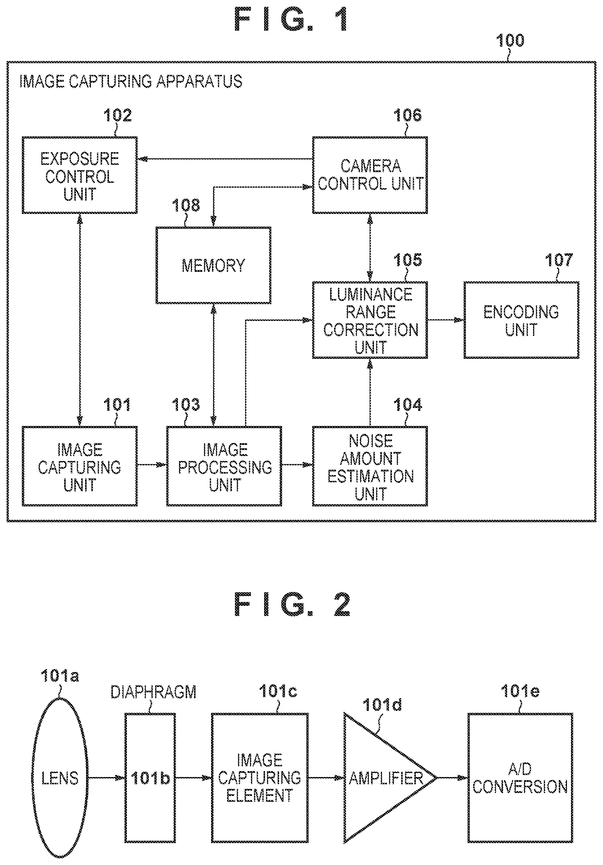
[0017]FIG. 1 is a block diagram illustrating a configuration of an image capturing apparatus 100 according to a first embodiment of the present invention.

[0018]The image capturing apparatus 100 includes an image capturing unit 101, an exposure control unit 102, an image processing unit 103, a noise amount estimation unit 104, a luminance range correction unit 105, a camera control unit 106, an encoding unit 107, and a memory 108.

[0019]As illustrated in FIG. 2, the image capturing unit 101 includes a lens 101a, a diaphragm 101b, an image capturing element 101c, an amplifier 101d, and an A / D converter 101e.

[0020]The lens 101a is configured by several lens groups as an image capturing optical system. The diaphragm 101b is used to adjust an amount of light incident on the image capturing element 101c via the lens 101a. The image capturing element 101c includes a CCD, a CMOS sensor, or the like, and converts a subject image formed through the lens 101a into an analog image signal. The a...

second embodiment

[0041]FIG. 5 is a block diagram illustrating a configuration of an image capturing apparatus 500 according to a second embodiment of the present invention. In the image capturing apparatus 500, the same functional units as those of the image capturing apparatus 100 of the first embodiment are denoted by the same reference numerals as those of FIG. 1, and a description thereof is omitted. As illustrated in FIG. 5, the image capturing apparatus 500 of the second embodiment includes a luminance distribution analysis unit 501 and an image quality priority setting unit 502 in addition to the configuration of FIG. 1.

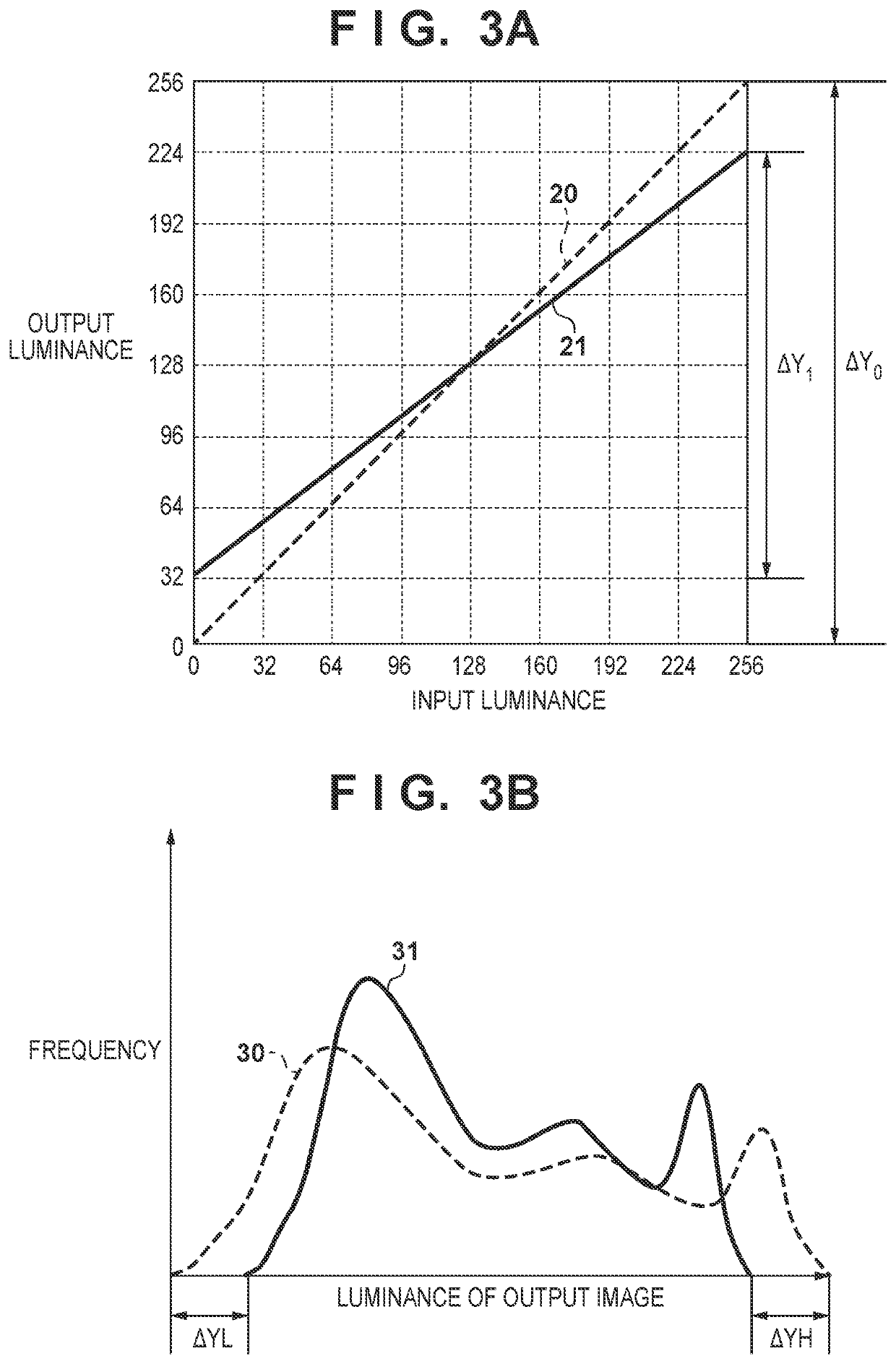
[0042]The luminance distribution analysis unit 501, with respect to the luminance distribution of the output image of the image processing unit 103 and based on a predetermined threshold value, calculates the frequency of a bright portion and the frequency of a dark portion. The image quality priority setting unit 502 sets the priority of the image quality.

[0043]In the first e...


PUM


Abstract

The image capturing apparatus includes an image capturing unit for capturing a subject image, a calculating unit for calculating an exposure amount at a time of capturing by the image capturing unit, a range correction unit for performing range correction for compressing a range of luminance in an image signal captured by the image capturing unit, an identification unit for identifying a luminance change amount of an image signal caused by range correction, and a changing unit for, based on the luminance change amount identified by the identification unit, changing at least one of the exposure amount and a reference luminance value in an input/output characteristic in a case of performing the range correction.

Description

BACKGROUND OF THE INVENTIONField of the Invention[0001]The present invention relates to an image capturing apparatus capable of reducing a code amount.Description of the Related Art[0002]When image capturing is performed by a camera in a low-illuminance environment, processing for increasing the gain of an image by Automatic Gain Control (AGC) is commonly performed. However, in this case, although the luminance of the image is increased, noise is increased, resulting in an image having a large code amount. In a surveillance camera requiring capturing and recording over a long time, since the size of the code amount leads to an increase in operation cost, it is necessary to generate an image with high encoding efficiency.[0003]Japanese Patent Laid-Open No. 2017-135554 discloses a technique for detecting illuminance at a time of capturing an image and correcting at least one of a minimum output luminance and a maximum output luminance of a correction characteristic for correcting a gr...

Claims


Application Information

Patent Timeline
Patent Type & Authority Applications(United States)
IPC IPC(8): H04N5/235
CPCH04N5/2351H04N5/2352H04N23/76H04N23/71H04N23/73H04N25/60H04N23/72
Inventor SUGAYA, ATSUTO
Owner CANON KK
Why Eureka
Try Eureka