Video image encoding device

a video image and encoding technology, applied in the field of video image encoding devices, can solve the problems of difficult to apply cabac which has a high computational cost compared to cavlc, lower compression efficiency of cavlc, and reduced code bits, so as to reduce the amount of code bits and increase compression rate

Active Publication Date: 2014-07-15
KOKUSA ELECTRIC CO LTD
View PDF7 Cites 20 Cited by
  • Summary
  • Abstract
  • Description
  • Claims
  • Application Information

AI Technical Summary

Benefits of technology

[0013]In view of the above, the present invention improves a compression rate in video encoding by particularly improving an encoding method of levels when variable length encoding is performed on image data.
[0018]In accordance with another aspect of the present invention, there is provided a video image encoding method including variable length encoding of performing variable length encoding on quantized transform coefficients which have been subjected to orthogonal transformation and quantization with respect to video image data on a region basis. Said variable length encoding executes a plurality of encoding modes for performing the variable length encoding on the quantized transform coefficients and performs the variable length encoding by using one of the encoding modes, and the encoding modes includes CAVLC(Context Adaptive Variable Length Coding), which includes performing fixed length encoding on each level_prefix of the quantized transform coefficients which is equal to or greater than a threshold value, such that each level prefix is distinguishable. In accordance with the present invention, when video image data is encoded, levels higher than a predetermined threshold value are encoded using fixed length, and therefore the compression rate can be increased by reducing the amount of code bits.

Problems solved by technology

Meanwhile, CAVLC has a compression efficiency lower than that of CABAC, but a computational cost thereof is lower than that of CABAC when encoding or decoding is performed.
Accordingly, at high bit rate, it is difficult to apply CABAC which has a high computational cost compared to CAVLC.
However, when CAVLC is applied at high bit rate due to the computational cost or the like, the following problems may be caused.
As described above, at a high bit rate, a problem arises in that the values of levels (quantized transform coefficients) increase and thus encoding efficiency decreases.

Method used


Image

  • Video image encoding device
  • Video image encoding device
  • Video image encoding device

Examples


Embodiment Construction

[0034]Embodiments of the present invention will be described in detail below with reference to the drawings.

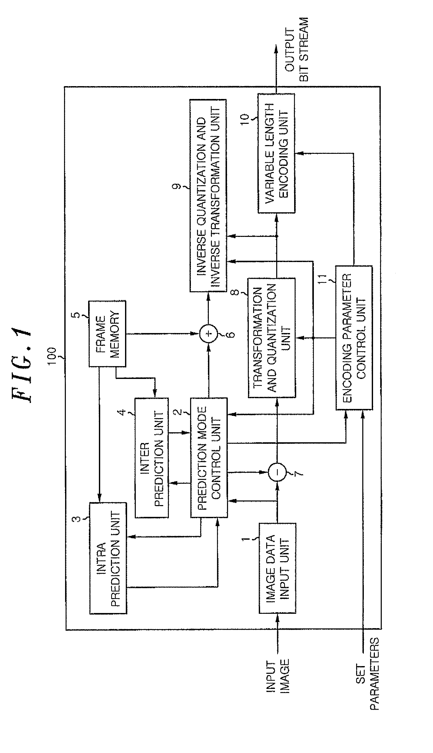
[0035]FIG. 1 is a functional block diagram showing an example of the overall configuration of a video encoding device 100 in accordance with an embodiment of the present invention. As shown in FIG. 1, the video encoding device 100 includes an image data input unit 1, a prediction mode control unit 2, an intra prediction unit 3, an inter prediction unit 4, a frame memory 5, an adder 6, a subtracter 7, a transformation and quantization unit 8, an inverse quantization and inverse transformation unit 9, a variable length encoding unit 10 and an encoding parameter control unit 11.

[0036]The image data input unit 1 receives video image data in a form of a plurality of macroblocks divided by an external signal processing device (not shown) such as an image block dividing unit and outputs the corresponding inputted video image data to the prediction mode control unit 2 and the subtract...


PUM


Abstract

In a variable length encoding for video data, the compression rate of video image encoding is increased by improving the level encoding method. A CAVLC encoding unit acquires coefficients obtained by orthogonally transforming and quantizing video image data in each block unit, determines an encoding mode of variable length encoding among those in a table_A and a table_B, or a mixture thereof by a level encoding mode controller and outputs the determination result to a level_prefix unit. In the table_B, a fixed_length bit string is allocated to a level_prefix which is at least a prescribed value. The level_prefix unit performs a level_prefix encoding in the determined encoding mode to output the result to an output control unit.

Description

[0001]This application is a Continuation-in-Part Application of PCT International Application No. PCT / JP2010 / 006008 filed on 7 Oct. 2010, which designated the United States.FIELD OF THE INVENTION[0002]The present invention relates to an encoding device for encoding image data or the like and, more particularly, to an encoding device that increases compression efficiency in a variable length encoding.BACKGROUND OF THE INVENTION[0003]Recently, in a video encoding technique, a video encoding device having functions, such as intra-picture prediction, inter-picture prediction, orthogonal transformation, quantization and variable length encoding, a representative of which is an MPEG (Moving Picture Experts Group), has been developed and put into practical application.[0004]In the above-described functions, the variable length encoding varies a length of code to be assigned to video data and assigns a code of shorter length to data appearing most frequently, the amount of the video data ha...

Claims


Application Information

Patent Timeline
Patent Type & Authority Patents(United States)
IPC IPC(8): H04N11/04H04N7/12H03M7/42H04N11/02H04N19/60H03M7/40H04N19/13H04N19/136H04N19/176H04N19/196H04N19/46H04N19/463H04N19/503H04N19/593H04N19/70H04N19/91
CPCH04N19/176H04N19/91H04N19/00951H03M7/42H04N19/00278H04N19/00218H04N19/159H04N19/00121H04N19/13
Inventor YAMAGUCHI, MUNEAKI
Owner KOKUSA ELECTRIC CO LTD
Why Eureka
Try Eureka