Liquid crystal display

a liquid crystal display and display frame technology, applied in the field of liquid crystal display apparatus, can solve the problems of not being able to perform overshoot driving in some cases, not being able being unable to achieve overshoot driving, so as to improve the viewing angle of the liquid crystal panel, the effect of suppressing the change in the luminance of the entire display fram

Inactive Publication Date: 2015-02-05
SHARP KK
View PDF7 Cites 4 Cited by
  • Summary
  • Abstract
  • Description
  • Claims
  • Application Information

AI Technical Summary

Benefits of technology

[0012]According to an embodiment of the present invention, it is possible to suppress a change in luminance of the entire display frame when overshoot driving is performed, while improving a viewing angle of a liquid crystal panel.

Problems solved by technology

For this reason, flicker is likely to be generated.
However, when the high gradation display and the low gradation display are switched between, it is not possible to perform overshoot driving in some cases.
Specifically, for example, in a case where the gradation after switching is a maximum gradation or a minimum gradation, it is not possible to perform overshoot driving.

Method used


Image

  • Liquid crystal display
  • Liquid crystal display
  • Liquid crystal display

Examples


embodiment

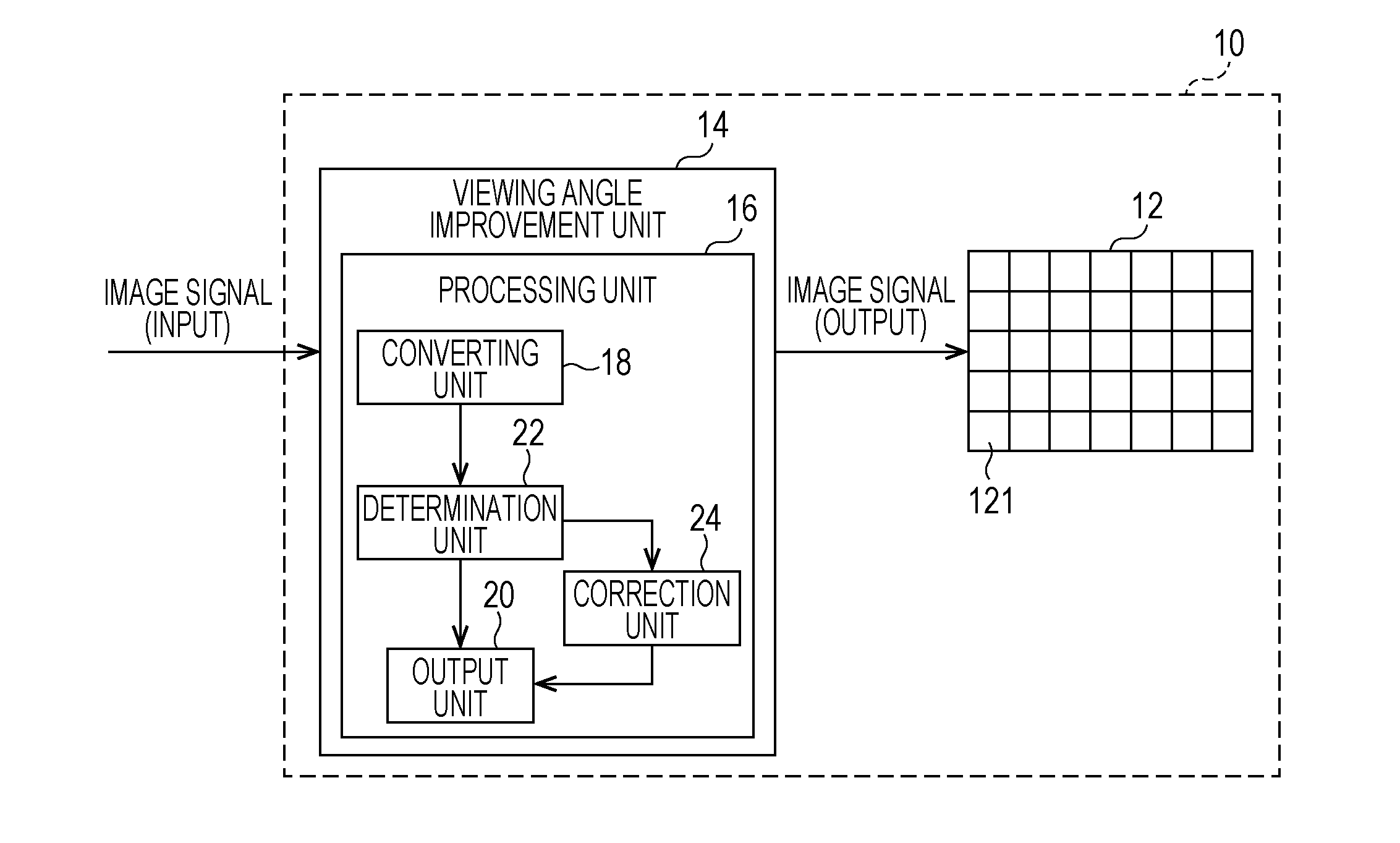
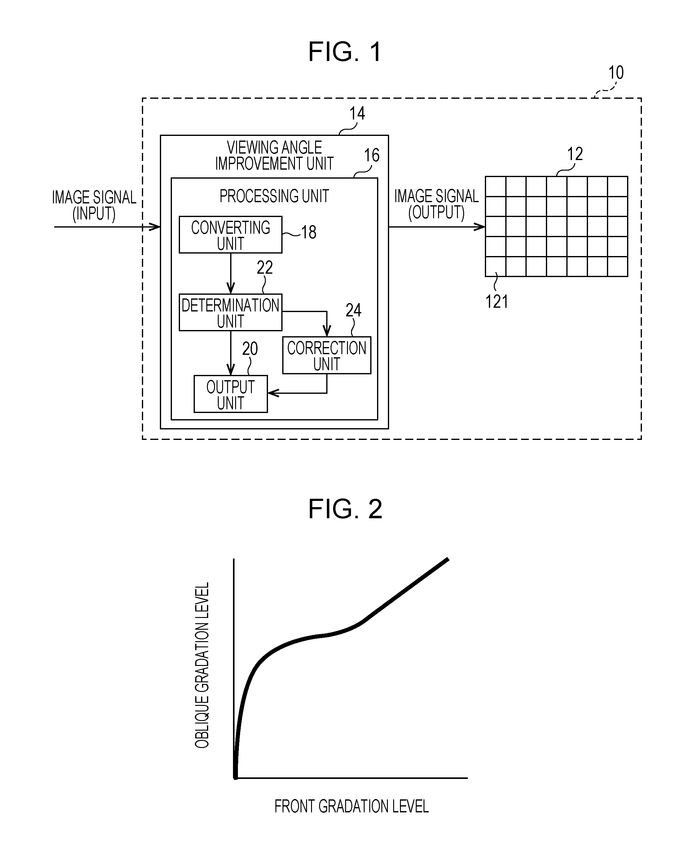
[0045]FIG. 1 shows a schematic configuration of a liquid crystal display apparatus 10 according to an embodiment of the invention. The liquid crystal display apparatus 10 includes a liquid crystal panel 12 and a viewing angle improvement unit 14. The viewing angle improvement unit 14 has a processing unit 16. The processing unit 16 has a converting unit 18, an output unit 20, a determination unit 22, and a correction unit 24. A source driver, a gate driver, and the like that drive the liquid crystal panel 12 are not shown in FIG. 1.

[0046]The liquid crystal panel 12 may be a liquid crystal panel of a transmission type, and may be a liquid crystal panel of a reflection type or a semi-transmission type. Operation modes of a liquid crystal in the liquid crystal panel 12 are not particularly limited.

[0047]The liquid crystal panel 12 has a plurality of pixels 121. The plurality of pixels 121 is disposed in a matrix pattern.

[0048]The liquid crystal panel 12 is not shown in the drawing, but...

application example 1 of embodiment

[0093]In the present application example, the determination unit 22 determines that overshoot driving cannot be performed even when a gradation of a high gradation display is a gradation close to a maximum gradation. Therefore, it is possible to make the luminance of the entire display frame close to a predetermined luminance.

application example 2 of embodiment

[0094]In the present application example, the determination unit 22 determines that overshoot driving cannot be performed even when a gradation of a low gradation display is a gradation close to a minimum gradation. Therefore, it is possible to make the luminance of the entire display frame close to a predetermined luminance.

[0095]The embodiments of the invention have been described in detail, but the embodiments are merely examples of the invention. The invention is not limited at all to the above-described embodiments at all.

[0096]For example, only when a gradation of an input image is an intermediate gradation, may the converting unit 18 convert the gradation of an input image to a gradation of a high gradation display and a gradation of a low gradation display.

[0097]In Table 1, in a case where the display mode 1 switches to the display mode 3 and in a case where the display mode 3 switches to the display mode 3, strong overshoot driving is performed. However, for example, in a c...


PUM


Abstract

In a display apparatus having a liquid crystal panel, a change in luminance of the entire display frame when overshoot driving is performed is suppressed, while improving a viewing angle of the liquid crystal panel. A processing unit performs a high gradation display displaying a gradation higher than a gradation of an input image at one of two adjacent pixels, performs a low gradation display displaying a gradation lower than a gradation of an input image at the other of the two adjacent pixels, and switches between the high gradation display and the low gradation display for each pixel every display frame. A correction unit corrects a gradation of a pixel located adjacent to a pixel displayed with a gradation for which predetermined overshoot driving is difficult in the next display frame to a gradation for which overshoot driving stronger than the predetermined overshoot driving is possible.

Description

TECHNICAL FIELD[0001]The present invention relates to a liquid crystal display apparatus including a liquid crystal panel, particularly, to a liquid crystal display apparatus having an improved viewing angle for a liquid crystal panel.BACKGROUND ART[0002]There is known a liquid crystal display apparatus provided with a liquid crystal panel. Improvement of a viewing angle of the liquid crystal panel for the liquid crystal display apparatus has been suggested. For example, an image processing method for changing a gradation in a time division manner (for example, every display frame) is disclosed in International Publication No. 2010 / 71221.[0003]In the image processing method described in the above-mentioned Publication, an image with a high gradation and an image with a low gradation are alternately displayed. Therefore, it is possible to improve the viewing angle of the liquid crystal display.[0004]However, if the image processing method described in the above-mentioned Publication ...

Claims


Application Information

Patent Timeline
Patent Type & Authority Applications(United States)
IPC IPC(8): G09G3/20G09G3/36
CPCG09G3/2007G09G3/36G09G2320/068G09G2320/0233G09G2320/0271G09G2320/0247G09G2320/028
Inventor MORI, TOMOHIKOTOMIZAWA, KAZUNARIHASEGAWA, MAKOTOYOSHIDA, YUICHI
Owner SHARP KK
Why Eureka
Try Eureka