Light emitting display device having normal and standby modes and driving method thereof

a light-emitting display and normal mode technology, applied in static indicating devices, instruments, electroluminescent light sources, etc., can solve the problems of short available usage time, small power consumption of organic light-emitting display devices, and inability to achieve normal and standby modes, so as to reduce power consumption and not deteriorate the quality of images.

Active Publication Date: 2021-03-23
LG DISPLAY CO LTD
View PDF8 Cites 4 Cited by
  • Summary
  • Abstract
  • Description
  • Claims
  • Application Information

AI Technical Summary

Benefits of technology

[0006]An aspect of the present invention is to provide an organic light emitting display device for reducing power consumption, and a method of driving the same.
[0007]Another aspect of the present invention is to provide an organic light emitting display device for suppressing a change in brightness so as to avoid deterioration in quality of an image, and a method of driving the same.
[0011]According to the present embodiments, an organic light emitting display device, which may reduce the power consumption, and an operating method thereof may be provided.

Problems solved by technology

Also, the organic light emitting display device is thin and light, and consumes a small amount of power, and thus, the organic light emitting display device has been widely utilized for mobile devices such as a smart phone, a tablet PC, and the like.
However, the mobile device is developed to be thin and light for convenient use, and thus, the battery may not be designed to have a large capacity, which leads to a short available usage time.

Method used


Image

  • Light emitting display device having normal and standby modes and driving method thereof
  • Light emitting display device having normal and standby modes and driving method thereof
  • Light emitting display device having normal and standby modes and driving method thereof

Examples


first embodiment

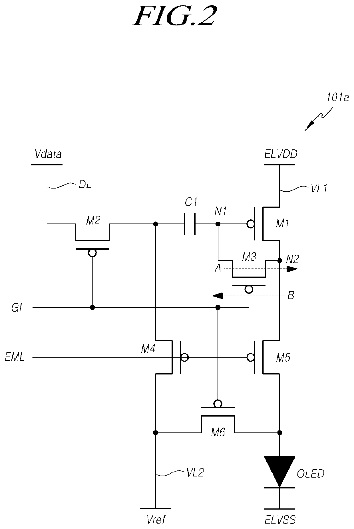
[0033]FIG. 2 is a circuit diagram illustrating the pixel of FIG. 1.

[0034]Referring to FIG. 2, the pixel 101 can include a pixel circuit 101a that generates a driving current, and an organic light emitting diode (OLED) that receives a driving current generated from the pixel circuit 101a and emits light. Also, the pixel circuit 101a can include a first transistor (M1) to a sixth transistor (M6). Also, the pixel 101 can include a first capacitor (C1). Each transistor can include a first electrode, a second electrode, and a gate electrode. The first electrode can be a source electrode and the second electrode can be a drain electrode. However, this may not be limited thereto. Also, although each transistor is illustrated as a transistor of a PMOS type, this may not be limited thereto. Also, the pixel circuit 101a can receive a first power source (ELVDD), a second power source (ELVSS), a data voltage (Vdata), a gate signal, and a light emission control signal (EM). Also, the pixel circu...

second embodiment

[0058]FIG. 4 is a circuit diagram illustrating the pixel of FIG. 1.

[0059]Referring to FIG. 4, the pixel 101 can include a pixel circuit 101b that generates a driving current and an organic light emitting diode (OLED). The pixel circuit 101b can receive a data voltage (Vdata), a gate signal, a light emission control signal (EML), an initialization control signal (IL), a voltage of a first power source (ELVDD), a voltage of a second power source (ELVSS), and an initialization voltage (Vref). Also, the pixel circuit 101b can include a first to sixth transistor (M1 to M6) and a first capacitor (C1). Here, the first transistor (M1) can be a driving transistor. Also, the first through sixth transistors (M1 to M6) each can include a first electrode, a second electrode, and a gate electrode. The first electrode can be a drain electrode, and the second electrode can be a source electrode. However, this may not be limited thereto. Also, the first to sixth transistors (M1 to M6) can be transis...

third embodiment

[0069]FIG. 5 is a circuit diagram illustrating a pixel employed by the organic light emitting display device of FIG. 1.

[0070]Referring to FIG. 5, the pixel 101 can include a pixel circuit 101c that generates a driving current and an organic light emitting diode (OLED). The pixel circuit 101c can receive a data voltage (Vdata), a first gate signal, a second gate signal, a light emitting control signal (EML), a voltage of a first power source (ELVDD), a voltage of a second power source (ELVSS), and an initialization voltage (Vref). Also, the pixel circuit 101d can include first to sixth transistors (M1 to M6) and a first capacitor (C1). Also, the first through sixth transistors (M1 to M6) can each include a first electrode, a second electrode, and a gate electrode. The first electrode can be a drain electrode, and the second electrode can be a source electrode. However, this may not be limited thereto. Also, the first to sixth transistors (M1 to M6) can be transistors of a PMOS type. ...


PUM


Abstract

An organic light emitting display device can include a display panel that expresses brightness based on a driving current corresponding to a data voltage, a power source unit that supplies power to the display panel, and a controller configured that outputs a mode control signal for determining a normal mode and a standby mode, drives the display panel to display a first frame for a first time period in the normal mode based on the mode control signal, and drives the display panel to display a second frame for a second time period that is longer than the first time period in the standby mode based on the mode control signal, in which the power source unit supplies a compensation voltage to at least one pixel during the standby mode for compensating a change in the data voltage in the pixel.

Description

CROSS-REFERENCE TO RELATED APPLICATION[0001]This application claims priority from Korean Patent Application No. 10-2016-0174333, filed in the Republic of Korea on Dec. 20, 2016, which is hereby incorporated by reference for all purposes as if fully set forth herein.BACKGROUND OF THE INVENTIONField of the Invention[0002]The present invention relates to an organic light emitting display device, and further relates to a method of driving the same.Description of the Related Art[0003]With the development of the information society, display devices for displaying images are being increasingly required in various forms, and various types of display devices, such as liquid crystal display (LCD) devices, plasma display devices, and organic light emitting display (OLED) devices, are utilized.[0004]Also, from among the display devices, an organic light emitting display device that employs an organic light emitting diode, which is a spontaneous light emitting device, may have an excellent color...

Claims


Application Information

Patent Timeline
Patent Type & Authority Patents(United States)
IPC IPC(8): G09G3/3233G09G3/3258H05B45/10H01L51/52H05B44/00
CPCG09G3/3233G09G3/3258H05B45/10G09G2300/0861G09G2310/0251G09G2310/0262G09G2320/0233G09G2320/0626G09G2330/022H01L51/5203G09G3/3225G09G2330/021H10K59/805G09G2230/00G09G2300/0842G09G2330/028G09G2300/043H10K50/805
Inventor LEE, YOUNGJOON
Owner LG DISPLAY CO LTD
Why Eureka
Try Eureka