Illumination apparatus and method

a technology of a rotary machine and a rotary machine, which is applied in the direction of lighting and heating equipment, lighting support devices, instruments, etc., can solve the problems of increasing the temperature, and increasing the frequency of electrical problems

Inactive Publication Date: 2007-07-10
EPISTAR CORP
View PDF7 Cites 138 Cited by
  • Summary
  • Abstract
  • Description
  • Claims
  • Application Information

AI Technical Summary

Problems solved by technology

Unfortunately, placing LEDs in a dense formation also undesirably increases the temperature of the LEDs, increasing the frequency of electrical problems.
The tradeoff between the desirable uniform light output and the undesirable temperature increase is a common problem faced by those in the industry when designing LED arrays.
The density of an LED array, and thus the quality of the light output, is directly limited by the heat dissipation around the LEDs.

Method used


Image

  • Illumination apparatus and method
  • Illumination apparatus and method
  • Illumination apparatus and method

Examples


Embodiment Construction

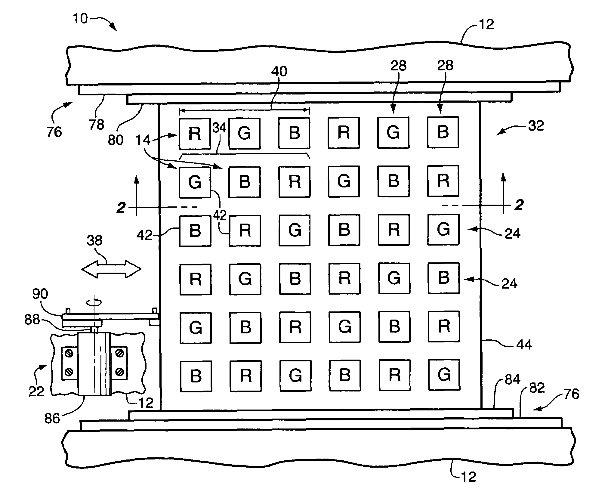
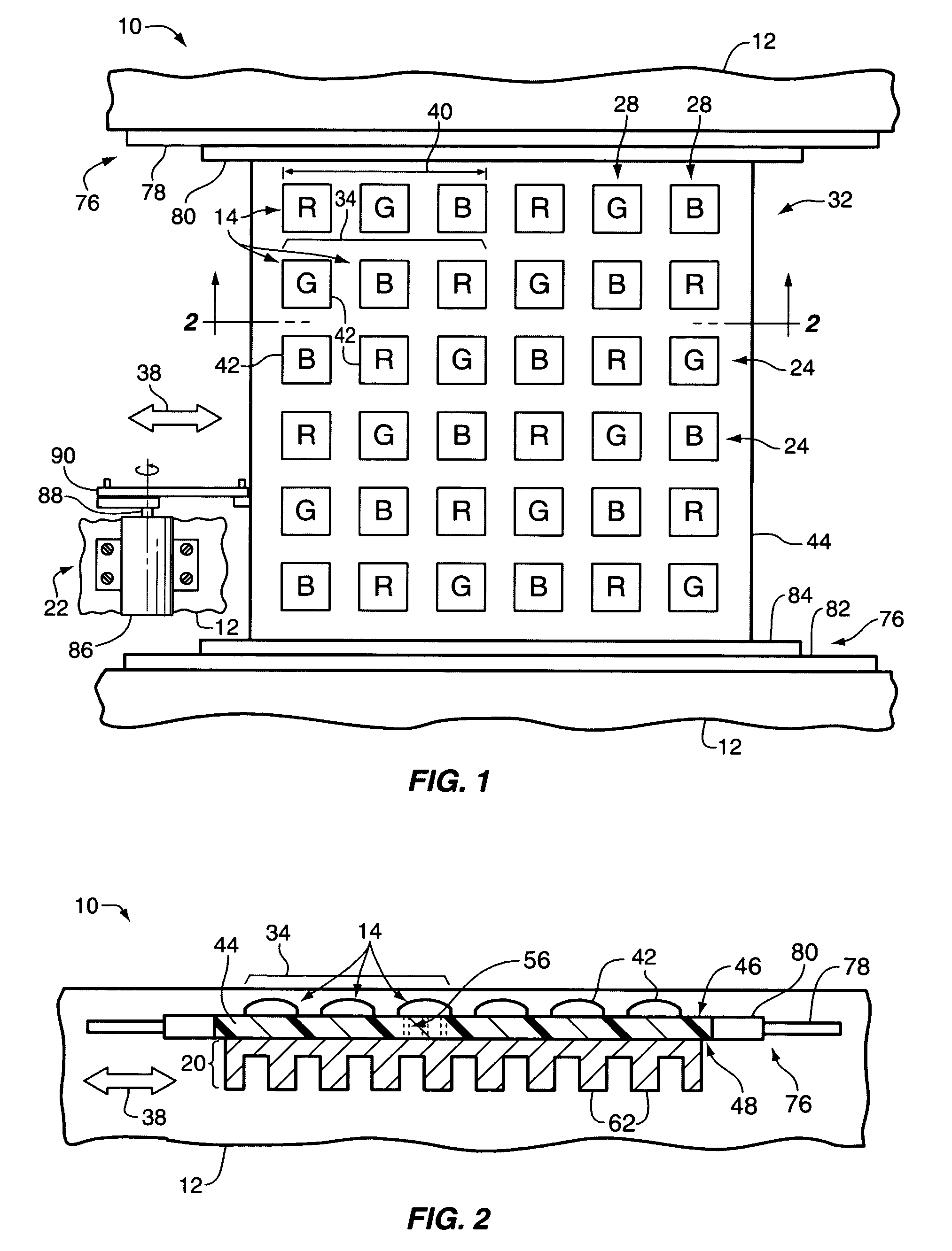
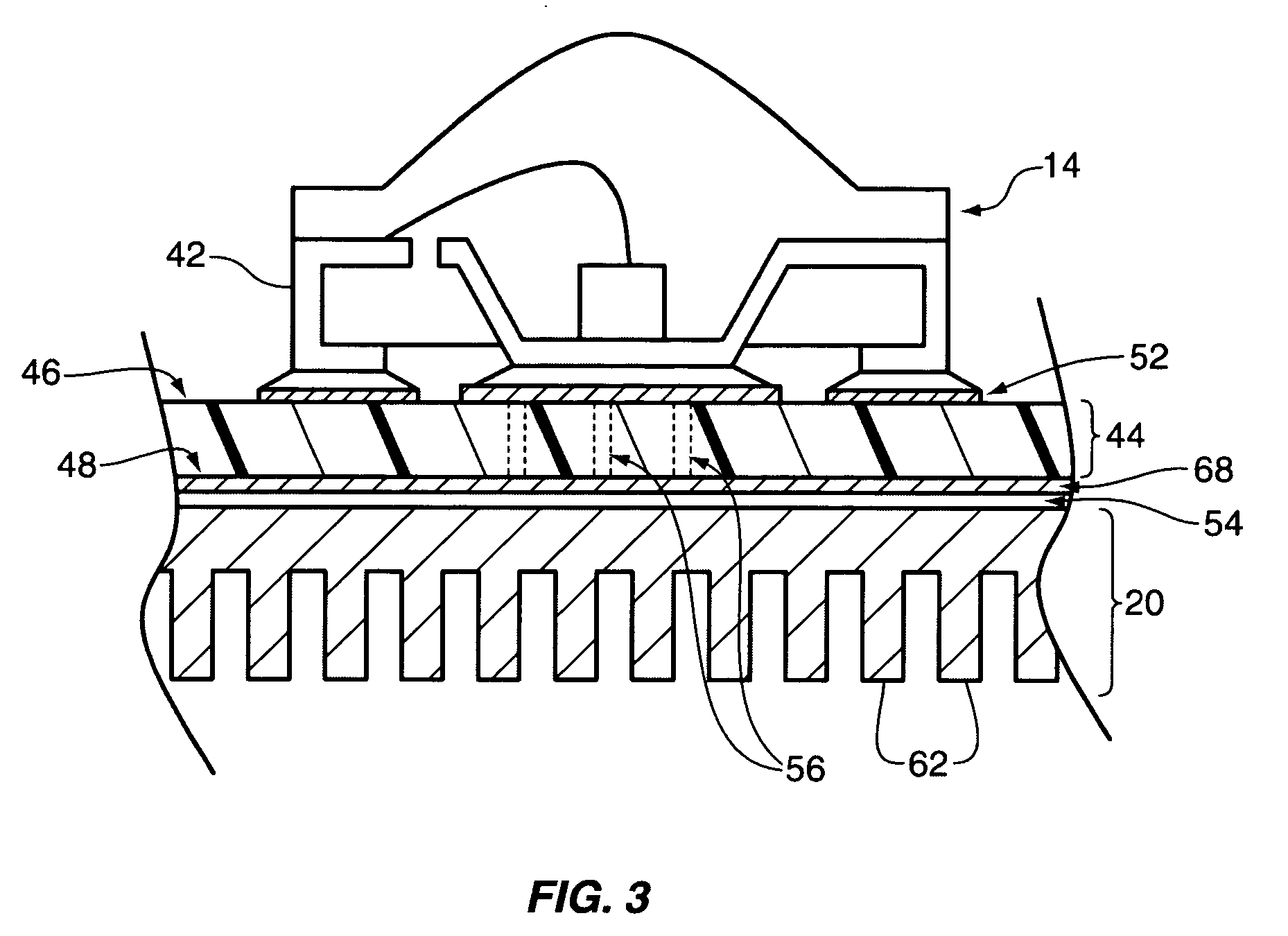
[0009]One embodiment of illumination apparatus 10 is best seen in FIGS. 1 and 2 and may comprise a support structure 12, at least one, and usually a plurality of light emitting elements 14, a heat sink 20, and an actuator system 22. The heat sink 20 is thermally coupled to the light emitting elements 14 and dissipates heat produced by the light emitting elements 14. The light emitting elements 14 and heat sink 20 are mounted so that they are moveable with respect to the support structure 12. In the embodiment shown and described herein, the light emitting elements 14 and heat sink 20 are moveable in one dimension (e.g., back and forth), generally in the directions indicated by arrows 38. The actuator system 22 is operatively associated with light emitting elements 14 and operates to move the light emitting elements 14 and heat sink 20 back and forth (i.e., generally in the direction indicated by arrows 38) with respect to support structure 12.

[0010]As will be described in greater de...


PUM


Abstract

Illumination apparatus includes a support structure, at least one light emitting element, and a heat sink thermally coupled to the light emitting element. The light emitting element and heat sink are moveable in relation to the support structure. An actuator system moves the at least one light emitting element and the heat sink with respect to the support structure.

Description

BACKGROUND[0001]Light emitting diodes, commonly called LEDs, are widely used in electronics today. LEDs perform many different functions in a wide variety of devices, including, among other things, numbers on digital clocks, illumination of traffic lights, transmitting information from remote controls, lighting up watches, and forming images on a television or computer screen. Placing LEDs in a dense formation generally results in more desirable uniform light output. Unfortunately, placing LEDs in a dense formation also undesirably increases the temperature of the LEDs, increasing the frequency of electrical problems. The tradeoff between the desirable uniform light output and the undesirable temperature increase is a common problem faced by those in the industry when designing LED arrays. The density of an LED array, and thus the quality of the light output, is directly limited by the heat dissipation around the LEDs.SUMMARY OF THE INVENTION[0002]The following summary is provided a...

Claims


Application Information

Patent Timeline
Patent Type & Authority Patents(United States)
IPC IPC(8): F21V29/00
CPCF21K9/00H05K1/0206G02F1/133603H05K2201/066H05K2201/10106H01L2224/48247H01L2224/48091H01L2924/00014F21S10/026F21V29/63F21Y2105/12F21Y2105/10
Inventor MOK, THYE LINNYOGANANADAN, SUNDAR NATARAJANLEE, KIAN SHINTAN, KHENG LENGPANG, SIEW ITKUAN, YEW CHEONGKARIM, NORFIDATHUL AIZAR ABDULOON, SU LINAFIF, FAKHRUL ARIFIN MOHDOU, WEN YA
Owner EPISTAR CORP
Why Eureka
Try Eureka