Cable restraint

a technology of cable restraint and cable release, which is applied in the direction of coupling device connection, electrical/magnetic/electromagnetic heating, and coupling parts engagement/disengagement, etc., can solve the problems of cable retention, plug release, electronic enclosure portability, and the difficulty of cable unplugging in the event of an emergency

Inactive Publication Date: 2007-07-10
GOOGLE LLC
View PDF6 Cites 21 Cited by
  • Summary
  • Abstract
  • Description
  • Claims
  • Application Information

AI Technical Summary

Problems solved by technology

Currently, users of power supplies for information technology (IT) applications encounter issues regarding cable retention, plug release, and electronic enclosure portability.
Cable retention may conflict with safety requirements that allow for a quick disconnect of a power cord from an electronic enclosure, such as a power supply, in the event of an emergency (smoke, electrical arcing, fire).
This solution has some drawbacks however, in that the user must know, and care, to allow for presence of a service loop (extra cable length) between the tie down and the electrical outlet.
Often, tie downs are installed without enough (or any) service loop, making it difficult for the cable to be unplugged in the event of an emergency.
Another known solution for cable retention is a “key ring.” This solution also includes some drawbacks, in that during installation of the cable, the customer may sometimes forget to feed the cable though the key ring.
After the power supply is turned on, one cannot feed the cable through the round ring without unplugging the cable, which requires a power down and / or risks a fault indication that must be cleared.
Referring to plug release difficulties in known plug-outlet associations, tightly packed electronic enclosure components can lead to small clearance access for grasping a plug.
If a user grabs the cable by the cable portion to pull the plug out of association with the outlet, this pulling can result in damage to the power cable.

Method used


Image

  • Cable restraint
  • Cable restraint
  • Cable restraint

Examples


Embodiment Construction

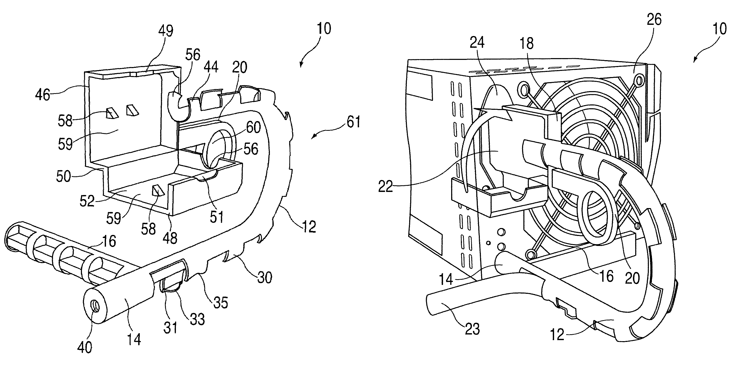
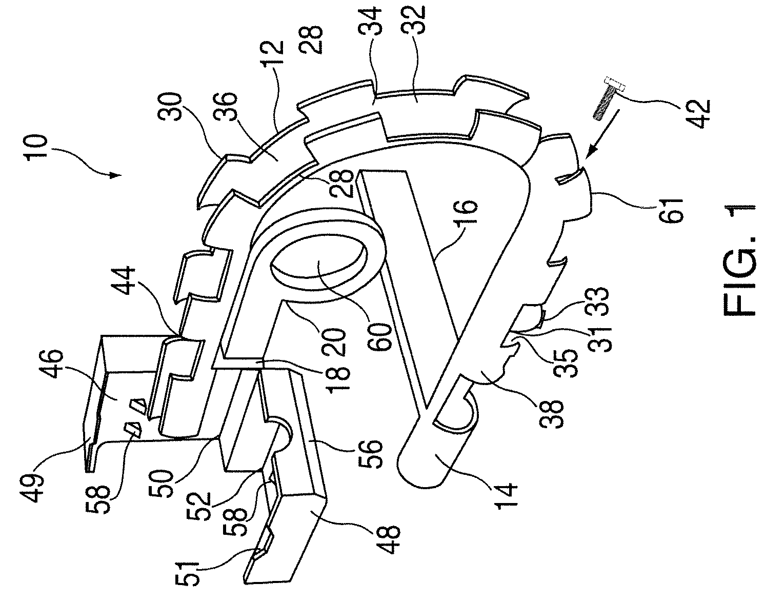
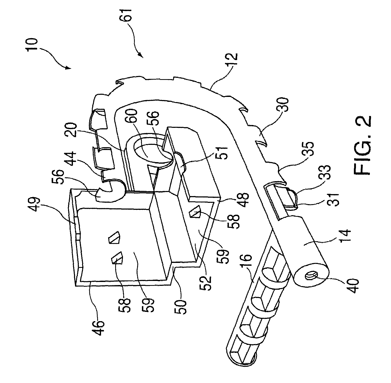
[0012]Referring to FIGS. 1–4, a cable restraint 10 is illustrated. The cable restraint 10 includes a flexible cable retainer 12, a tie down portion 14, a unit removal handle 16, a plug enclosure 18, and a pull handle 20. The cable restraint 10 is configured to facilitate retention of an association between a plug 22 of a cable 23 and an outlet 24 of an electronic enclosure 26 (such as an AC power supply). In addition, the cable restraint 10 is configured to allow for a convenient and rapid release of the plug 22 from the outlet 24, particularly in an emergency situation such as smoke, electrical arcing, fire. The cable restraint 10 is further configured to provide a mechanism by which the electronic enclosure 26 may be transported.

[0013]The flexible cable retainer 12 comprises a cable retaining body 28 and a plurality of cable grips 30 that extend from the cable retaining body 28. The cable retaining body 28 and the cable grips 30 define a cable cavity 32 and a flexible cable entry ...


PUM


Abstract

Disclosed is cable restraint including a flexible and resilient cable retainer including a cable retaining body and a plurality of cable grips, the body and grips defining a cable cavity that is contoured to partially house a cable, a tie down portion extending from a tie down end of the cable retainer, the tie down portion being configured to allow association of the tie down portion with an electronic enclosure, a portability handle extending from the tie down portion, a plug enclosure including a first enclosure portion and a second enclosure portion that is hinged to the first portion, and the second portion being rotatable into enclosing association with the first portion to form and define a plug cavity for disposal of a plug and a plug opening that allows the plug to associate with the electronic enclosure, and a pull handle extending from the first end portion.

Description

BACKGROUND OF THE INVENTION[0001]1. Field of the Invention[0002]The disclosure relates generally to a cable restraint, and more particularly to a cable restraint that is associable with an electronic enclosure.[0003]2. Description of the Background[0004]Currently, users of power supplies for information technology (IT) applications encounter issues regarding cable retention, plug release, and electronic enclosure portability. Cable retention pertains to prevention of inadvertent unplugging of a cable plug. Cable retention may conflict with safety requirements that allow for a quick disconnect of a power cord from an electronic enclosure, such as a power supply, in the event of an emergency (smoke, electrical arcing, fire). One known solution for cable retention is a cable tie down. This solution has some drawbacks however, in that the user must know, and care, to allow for presence of a service loop (extra cable length) between the tie down and the electrical outlet. Often, tie down...

Claims


Application Information

Patent Timeline
Patent Type & Authority Patents(United States)
IPC IPC(8): H01R13/56B01J19/12H05B6/68
CPCB01J19/126H05B6/666H05B6/686H05B6/70H05B6/705H05B6/806B01J2219/1218B01J2219/1275B01J2219/1281
Inventor COX, AARON R.CURNALIA, MICHAEL A.MINYARD, JASON A.
Owner GOOGLE LLC
Why Eureka
Try Eureka