Branched spike bird deterrent

a bird deterrent and spike technology, applied in the field of bird deterrents, can solve the problems of noisy noise, unsightly mess, and device may be too expensive to manufactur

Inactive Publication Date: 2007-07-17
BIRD B GONE
View PDF18 Cites 63 Cited by
  • Summary
  • Abstract
  • Description
  • Claims
  • Application Information

AI Technical Summary

Problems solved by technology

Unfortunately, when birds perch, they tend to be noisy and make an unsightly mess.
There is a tradeoff, however, with respect to the spacing of the spikes.
If the spikes are too close together, the device may be too expensive to manufacture.

Method used


Image

  • Branched spike bird deterrent
  • Branched spike bird deterrent
  • Branched spike bird deterrent

Examples


Embodiment Construction

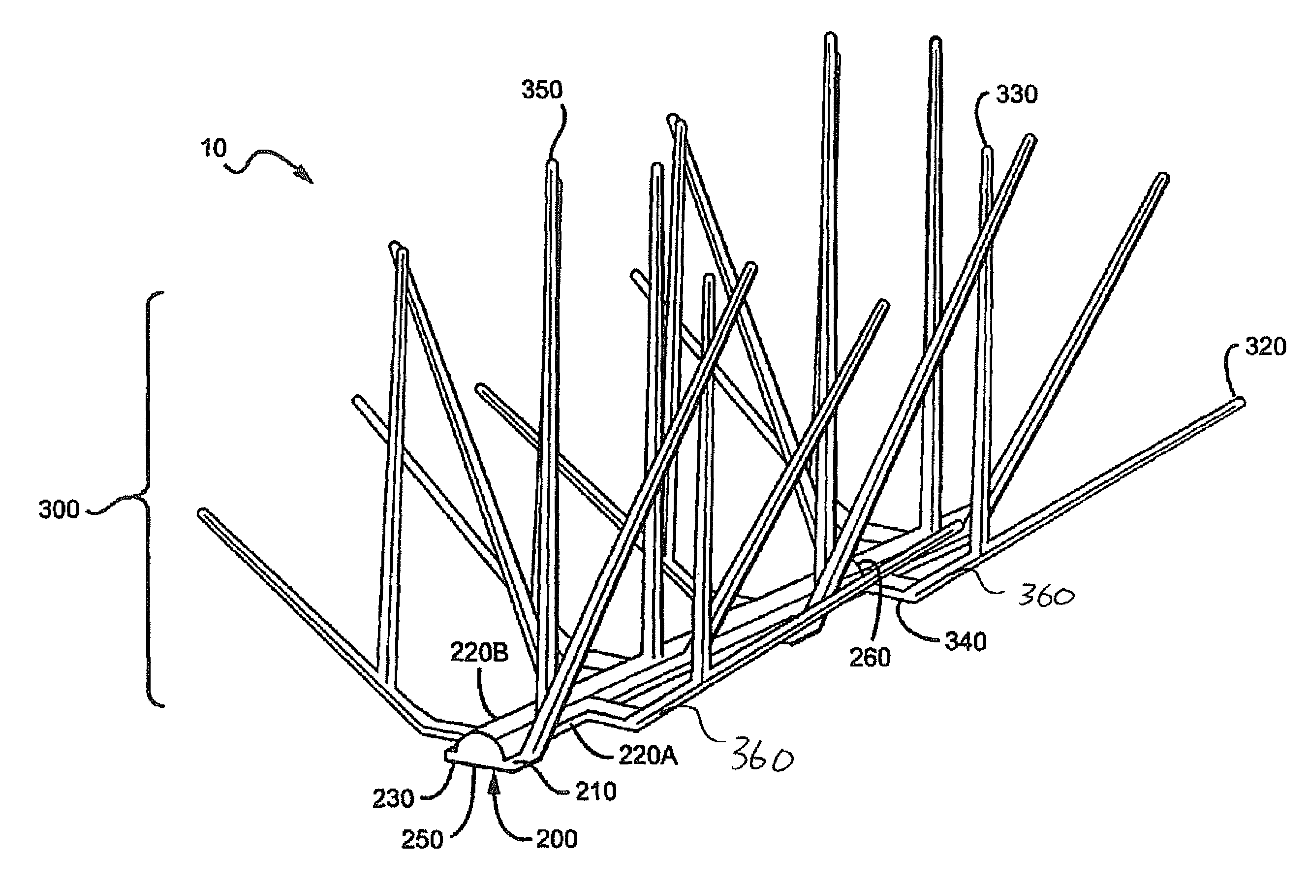
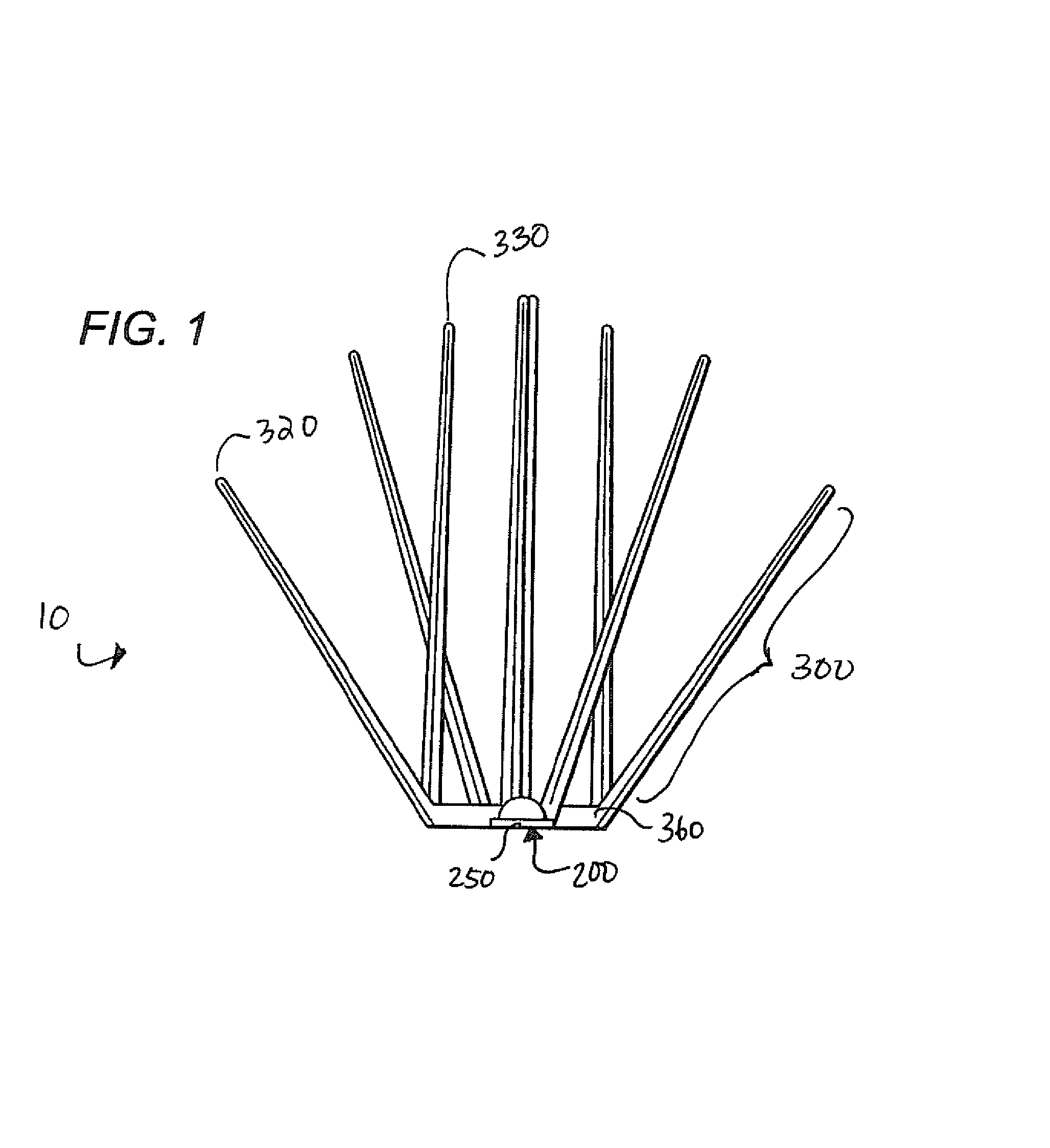
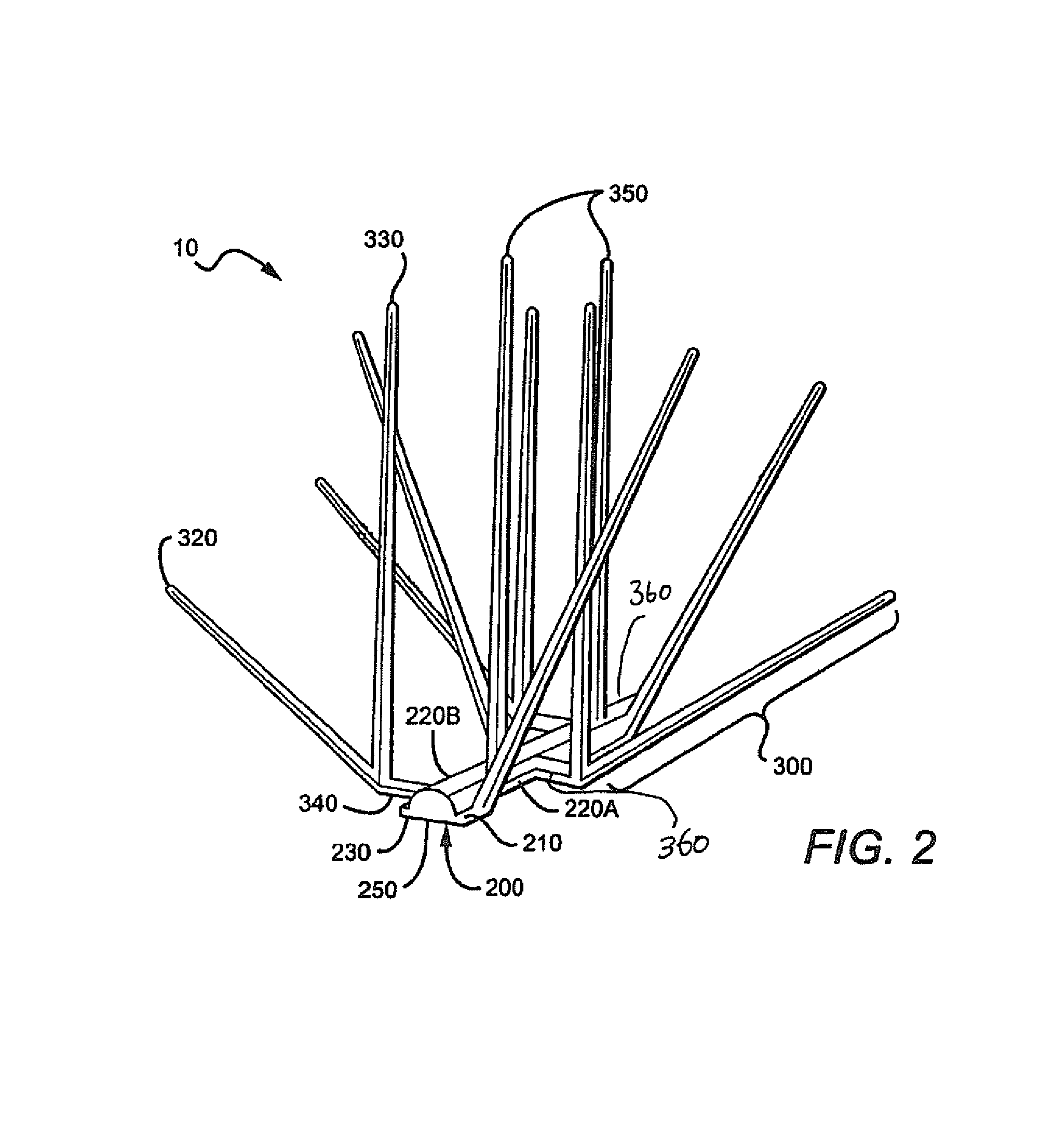
[0009]In FIGS. 1, and 2, a bird deterent 10 generally has a base 200 and a plurality of branched spikes 300. Each bracnhed spike 300 has two top ends 320, 330, and a bottom end 340. The base 200 has a top 210, two sides 220A, 220B, and a bottom 230.

[0010]As used herein, the term “branched spike” refers to a spike with at least three ends; in the figures two top ends 320, 330 and a bottom end 340, and the term “branch” refers to the intersection of at least two portions of the branched spike. Thus, bending a normal double-ended spike does not transform it into a “branched spike as the term is employed herein.

[0011]Within this broad definition, there is tremendous room for variation. For example, although a typical branched spike 300 contains a single branch point leading to two top ends, contemplated spikes (not shown) could contain branch points that lead to three or even more four top ends. It is also contemplated that a single spike can have multiple branching points, i.e., a bran...


PUM

PropertyMeasurementUnit
branch angleaaaaaaaaaa
branch anglesaaaaaaaaaa

Abstract

A bird deterrent has a base and at least one branched spike extending from the base. The branching can occur anywhere along the spike, and a single branch point can give rise to multiple branches. Spikes can have multiple branches. The various branches can be of any suitable length(s), and can be oriented in any suitable direction(s).

Description

FIELD OF THE INVENTION[0001]The field of the invention is bird deterrents.BACKGROUND OF THE INVENTION[0002]Birds like to perch in various places including rooftops, ledges, and other areas on commercial buildings and residences. Unfortunately, when birds perch, they tend to be noisy and make an unsightly mess.[0003]Birds can be deterred from landing through the use of mechanical bird deterrents. Especially useful such devices have a plurality of spikes that extend in different directions from a base support, as seen in FIG. 1. Numerous variations have been introduced over the years, including variations in the type of material (plastic, wire, etc) used for the spikes, the way the spikes are attached to the base, and the way the spikes are fanned out from the base. These and other variations are described in U.S. Pat. No. 6,775,950 entitled “Double Bend and Crush Bird Deterrent Device”, issued on Aug. 17, 2004, which is incorporated herein by reference in its entirety.[0004]There is ...

Claims


Application Information

Patent Timeline
Patent Type & Authority Patents(United States)
IPC IPC(8): E04B1/72E04H9/16A01M29/32
CPCA01M29/32E04B1/72Y10S119/903B29C45/0001B29C45/0081B29C45/2626B29K2069/00B29L2031/008B29L2031/10
Inventor DONOHO, BRUCE
Owner BIRD B GONE
Why Eureka
Try Eureka