Mode seeding cathode for a relativistic magnetron

a technology of relativistic magnets and cathodes, which is applied in the direction of magnets, electric discharge tubes, oscillation generators, etc., can solve the problems of not being the desired energy-efficient pi mode, excessive noise, and several problems of devices

Inactive Publication Date: 2007-07-17
AIR FORCE GOVERNMENT OF THE UNITED STATES THE AS REPRESENTED BY THE SERETARY OF THE
View PDF3 Cites 13 Cited by
  • Summary
  • Abstract
  • Description
  • Claims
  • Application Information

AI Technical Summary

Problems solved by technology

These devices are plagued by several problems.
It is not uncommon for current devices to take 150 nanoseconds or more to lock into a mode, and even then it may not be the desired energy-efficient pi mode.
Another problem is mode competition, particularly for higher values of axial magnetic field.
The excitation of

Method used


Image

  • Mode seeding cathode for a relativistic magnetron
  • Mode seeding cathode for a relativistic magnetron
  • Mode seeding cathode for a relativistic magnetron

Examples


Embodiment Construction

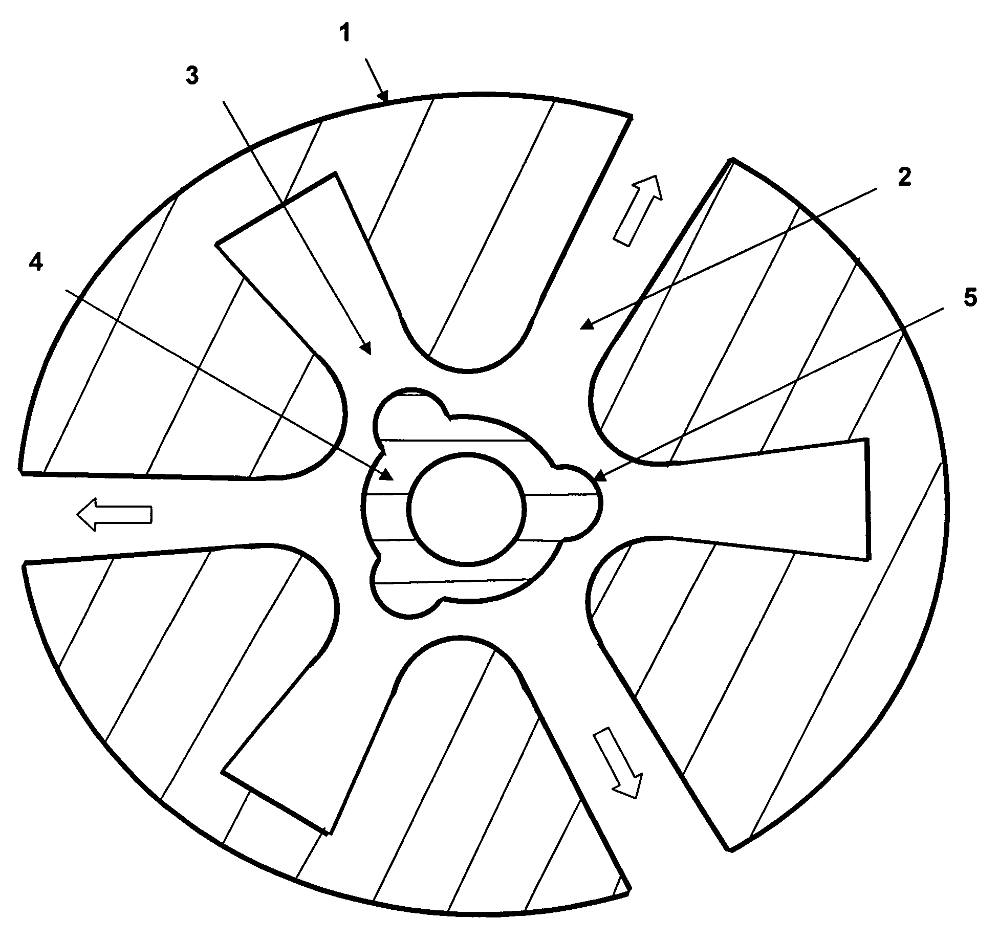
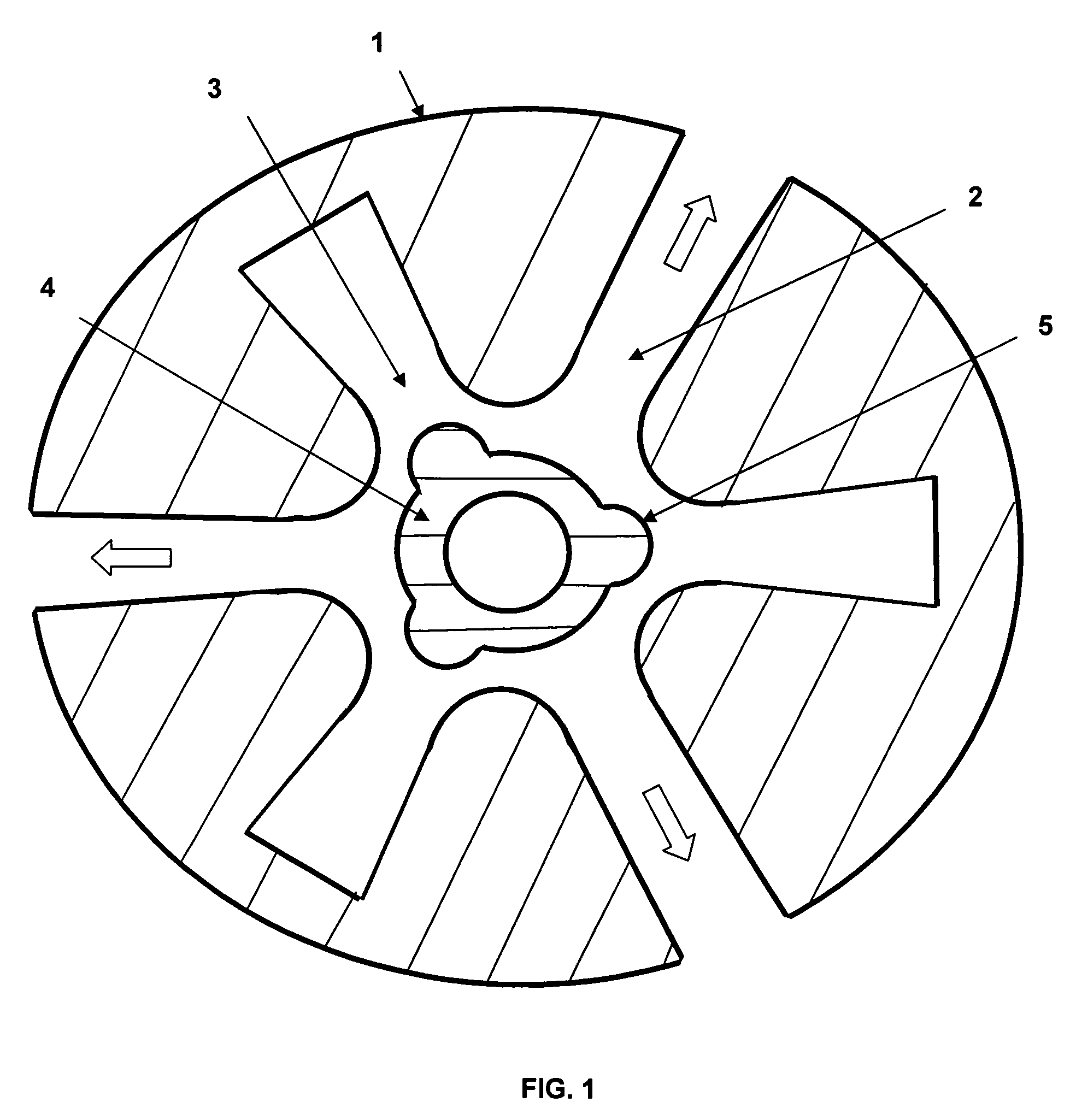
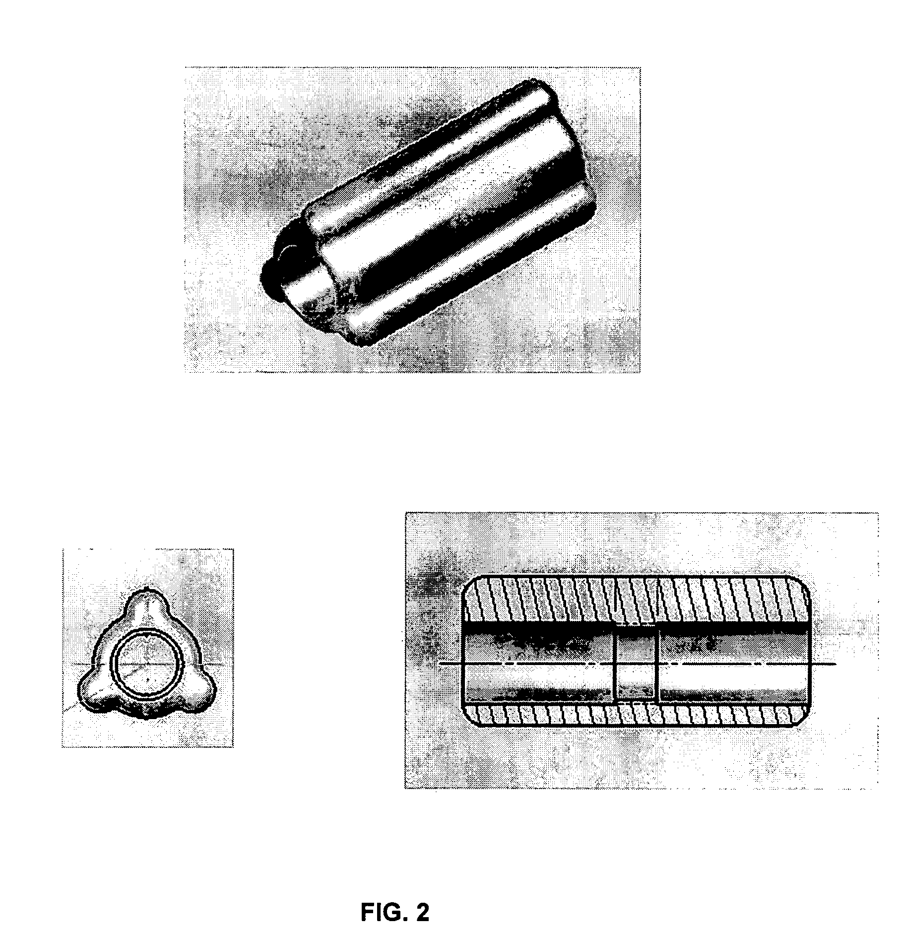
[0016]An embodiment of the invention uses a modification of the cathode geometry to prime high-power relativistic magnetrons, thereby causing preferential selection of the pi mode at startup. The cathode geometrical priming reduces mode competition and lock-in time while increasing the power output and efficiency of relativistic magnetrons operated at both low and high axial magnetic fields. The preferential selection of the pi mode at startup is achieved by shaping the cathode to form a DC electric field that has a non-negligible azimuthal component. The azimuthal component aids in the early development of the magnetron instability. The geometry of the shaped field is made to resemble the desired pi mode. With these cathode enhancements the range of parameters over which the relativistic magnetron may operate is greatly increased.

[0017]FIG. 1 is an axial top-down view of an A6 relativistic magnetron, here used as an example. The A6 has six cavities, three extraction cavities and th...


PUM


Abstract

A high-power relativistic magnetron wherein the cathode geometry is shaped to form a DC electric field that has a non-negligible azimuthal component causing preferential selection of the pi mode at startup (suppression of mode competition), a significant increase in radiated power output and time integrated efficiency when compared to standard relativistic magnetron cathode designs.

Description

STATEMENT OF GOVERNMENT INTEREST[0001]The conditions under which this invention was made are such as to entitle the Government of the United States under paragraph I(a) of Executive Order 10096, as represented by the Secretary of the Air Force, to the entire right, title and interest therein, including foreign rights.BACKGROUND OF THE INVENTION[0002]High power relativistic magnetrons are devices that emit microwave radiation in short pulses. These devices are plagued by several problems. Because these devices operate in a pulse mode and the pulse lasts only a few hundred nanoseconds, any reduction in the amount of time it takes to achieve mode lock significantly increases efficiency. It is not uncommon for current devices to take 150 nanoseconds or more to lock into a mode, and even then it may not be the desired energy-efficient pi mode. Another problem is mode competition, particularly for higher values of axial magnetic field. The excitation of modes other than the pi mode result...

Claims


Application Information

Patent Timeline
IPC IPC(8): H01J25/50H01J23/05
CPCH01J23/05H01J25/50
Inventor FLEMING, TIMOTHY P.
Owner AIR FORCE GOVERNMENT OF THE UNITED STATES THE AS REPRESENTED BY THE SERETARY OF THE
Why Eureka
Try Eureka