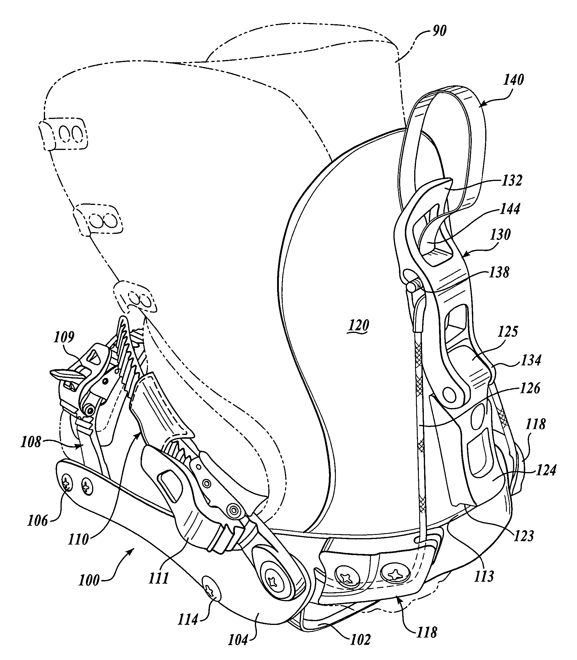
Snowboard binding engagement mechanism

a technology of binding and mechanism, which is applied in the direction of snowboard bindings, sports equipment, transportation and packaging, etc., can solve the problems of increasing the difficulty of moving the lever between the released, affecting and affecting the safety of the rider, so as to facilitate the entry of the boo

Inactive Publication Date: 2007-07-24
K 2 CORP
View PDF17 Cites 73 Cited by
  • Summary
  • Abstract
  • Description
  • Claims
  • Application Information

AI Technical Summary

Problems solved by technology

The engagement lever is positioned on the rear surface of the highback and accessibility may be further limited by other gear and ice on the rider's gear.
Each of these aspects increases the difficulty of moving the lever between the released and the locked position.
In addition, the lever can be difficult for the rider to grab because its position in the unlocked position is very low to the ground, near the surface of the snowboard.
Therefore, it can be difficult to physically reach to the end of the lever to engage the binding.
The low-profile shape is not ideal for grabbing onto the lever for engagement or disengagement of the binding.
These efforts, however, have proved ineffective or impractical.
For example, larger levers add to the weight and expense of the binding and tend to expose the mechanism to external forces that may cause the lever to inadvertently disengage, and rubberized levers do not adequately address difficulties associated with accessing the lever.

Method used


Image

  • Snowboard binding engagement mechanism
  • Snowboard binding engagement mechanism
  • Snowboard binding engagement mechanism

Examples


second embodiment

[0034]In this second embodiment, a semirigid, flexible panel 202 is attached to the back of the highback 120. The proximal end of the panel 202 is fixed between the blocking member 124 and the highback 120 and extends upwardly from the blocking member 124. A guide element 204 defining an aperture therethrough is attached to the distal end of the flexible panel 202. One end portion 205 of a flexible cord 206 is attached to the locking lever 130 at an intermediate position on the locking lever 130. The cord 206 extends upwardly through the aperture in the guide element 204. A relatively large, graspable element 210 is attached at a second end portion 207 of the cord 206. In the current embodiment, the graspable element 210 is a sewn leather loop, although other suitable materials may be used—including, for example, a polymeric material, a sturdy fabric element, and the like. The cord 206 may be formed from a natural fiber or synthetic material, for example, or metal cable or the like....

third embodiment

[0038]the present invention is shown in FIG. 5, which shows a side view of the rearward portion of a binding 300 having a base plate 302 with a pair of oppositely-disposed, fixed sidewalls 304 (one shown) that may be formed as integral parts of the base plate 302 or fixedly attached to the base plate 302. In this embodiment of the binding 300, the sidewalls 304 are not pivotable and the highback 320 is pivotably attached directly to the sidewalls 304 by a pivot member 305. A separable heel loop is not required. A cable 326 extends from a fixed attachment at an intermediate position 303 on one of the sidewalls 304, rearwardly and behind the highback 320 to slidably engage a locking lever 330, and around to the sidewall 304 on the opposite side (not visible). The locking lever 330 is movable between a locked position, shown in FIG. 5, and an open position, shown in phantom. Typically, the cable 326 effective length is adjustable—for example, with a threadable attachment at 303 (not sh...


PUM


Abstract

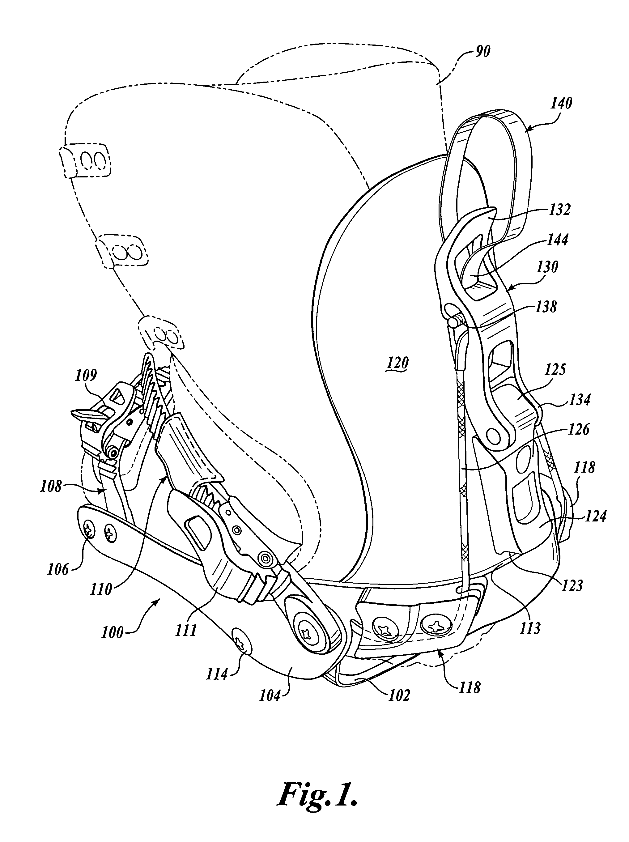
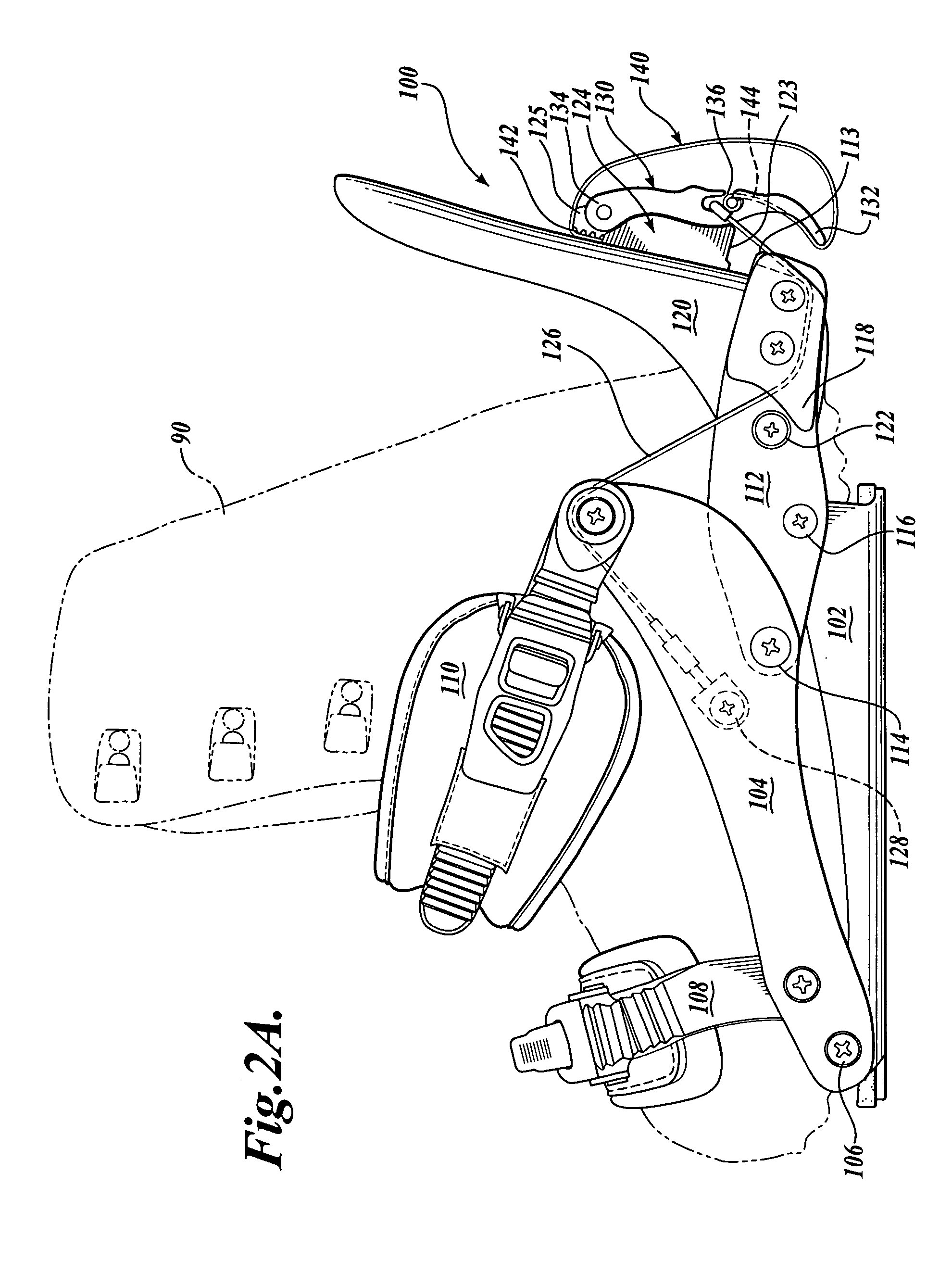
A snowboard binding (100) is disclosed having a base plate (102) with a highback (120) pivotally attached. A locking lever (130) is disposed on the back of the highback for locking the highback in a generally upright position with a desired maximum forward lean. A flexible member such as a strap (140) or a panel (202), cord guide (204), and cord (206) attached to the highback and to the locking lever to facilitate moving the lever between an open position and a locked position. In an embodiment of the invention, the base plate includes a pair of oppositely-disposed, pivotable sidewalls (104) and the highback is attached to the base plate with a heel loop (112) that pivotably engages the sidewalls, such that straps (108, 110) mounted to the sidewalls move to engage the boot (90) when the highback is moved to an upright position.

Description

FIELD OF THE INVENTION[0001]The present invention is in the field of bindings for sports equipment and, in particular, to bindings for snowboards.BACKGROUND OF THE INVENTION[0002]Gliding boards, primarily for sporting activities, are well known in the art and in the sporting world, including snowboards, snow skis, water skis, and the like. Various types of bindings have been developed to allow the user to engage the gliding board. The present disclosure is described with reference to the currently preferred snowboard binding embodiments, although the present invention may readily be adapted for other gliding board applications.[0003]Conventional snowboard binding systems used with soft snowboard boots are generally categorized as either strap bindings that typically include a rigid highback piece against which the heel of the boot is placed and one or more straps that secure the boot to the binding, or step-in bindings that typically utilize one or more strapless engagement members ...

Claims


Application Information

Patent Timeline
Patent Type & Authority Patents(United States)
IPC IPC(8): A63C9/00
CPCA63C10/04A63C10/045A63C10/06A63C10/24
Inventor MARTIN, JOHN D.
Owner K 2 CORP
Why Eureka
Try Eureka