Electronic paper file

a technology of electronic paper and file, applied in the field of electronic paper file, can solve the problems of inconvenient environment and difficulty for users to obtain spaces for inputting or displaying information

Inactive Publication Date: 2007-07-24
PANASONIC CORP
View PDF28 Cites 71 Cited by
  • Summary
  • Abstract
  • Description
  • Claims
  • Application Information

AI Technical Summary

Benefits of technology

[0014]According to the configuration provided with the above-mentioned means, it is possible to provide the electronic paper file with an advantage like a book or a notebook as well as the communication function. The electronic paper file can resolve a conventional problem that the display region of the portable terminal is small.
[0016]The above-mentioned configuration can allow a user to use a large region instead of such conventional communication along with dividing one screen into two, as well as the data to be managed with ease.
[0018]Moreover, if the electronic paper is attached to the electronic paper file removably, it makes easy to manage the data per electronic paper.
[0020]Such arrangement makes it possible to facilitate the use of the electronic paper because of more precise setting of functions.
[0021]And after an ID number for specifying an electronic paper is imparted to the electronic paper, the page management means may send the data to the electronic paper according to the ID number. For instance, when a user inputs to the page management means an ID number of an electronic paper to which he wants to send a data, the page management means can obtain the data to be displayed and send the data to the electronic paper specified by the user. In order that the user recognize the ID number with ease, the electronic paper file may be provided with an ID number obtaining means for obtaining the ID number.
[0022]To manage efficiently a plurality of electronic papers, the electronic paper file may be provided with a setting means for setting an electronic paper to a specific group according to the ID number. After setting a group according to the ID number, the setting means creates a mark to identify the group and sends to the electronic paper the display data to display the group mark. The electronic paper, on receiving the display information, displays the mark.

Problems solved by technology

Therefore, the display has to be divided in order to browse the data consisting of plural documents or to input more data referring to a specific document, which may be an inconvenient environment.
Accordingly, it is very hard for each user to obtain spaces for inputting or displaying his information for which the user makes a note or browses a different page for his own benefit.

Method used


Image

  • Electronic paper file
  • Electronic paper file
  • Electronic paper file

Examples


embodiment 1

[0087]The explanation here relates to the communication between an electronic paper file 30A of a user A and an electronic Paper file 30B of a user B.

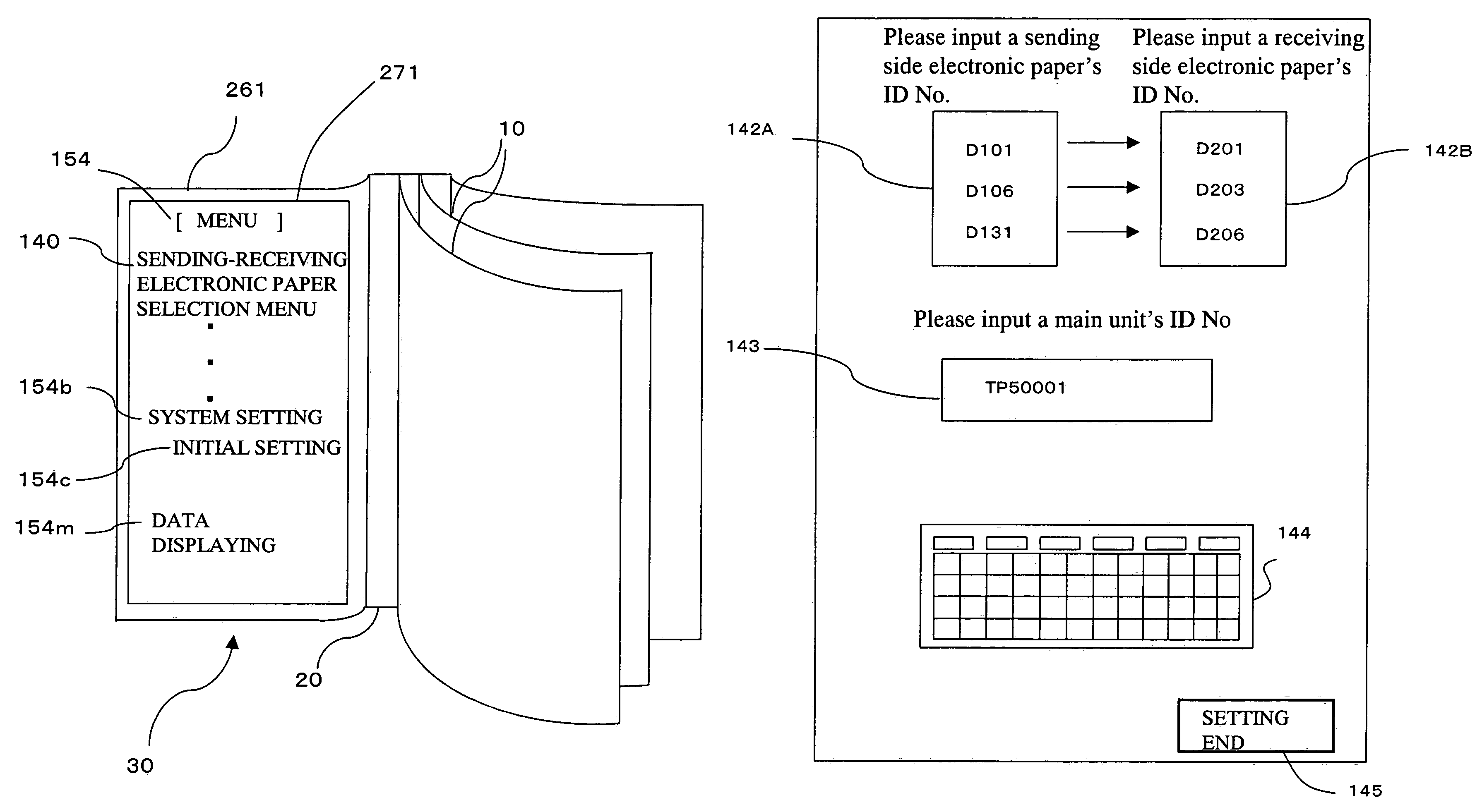
[0088]When the user A turns the electronic paper file 30A on power, an input means 130 is activated and a menu 154 is displayed on a cover display 271 arranged on the backside of the covet 26 to inbut same items reciuired on operating as shown in FIG. 3. The user selects a sending-receiving electronic paper selecting menu 140 out of the menu 154 by means of the writing device 14.

[0089]At this time, a sending-receiving electronic paper setting means 141 of the main unit 20 displays on the cover display 271 an input spaces 142A and 143 as shown in FIG. 4, said input space 142A for inputting an ID number of a sending side electronic paper 7A of which content is sent to the electronic paper 30B, and said input space 143 for inputting an ID number of the main unit 20 of the electronic paper file 30B which is a destination of the content.

[00...

embodiment 2

[0135]Like the embodiment 1, the user A specifies the sending side electronic paper 7A among the electronic papers 10 of the electronic paper file 30A, as well as the user B specifies the receiving side electronic paper 8B among the electronic papers 10 of the electronic paper file 30B.

[0136]In addition to the above steps, the users A and B take following steps in this embodiment. The user B specifies from the electronic papers 10 of the electronic paper file 30B a sending side electronic paper 7B of which display content is sent to the electronic paper file 30A, as well as the user A specifies from the electronic papers 10 of the electronic paper file 30A a receiving side electronic paper 8A corresponding to the sending side electronic paper 7B specified by the user B. According to such steps, the sending side and receiving side electronic papers are set on the respective electronic paper files 30A and 30B of the users A and B.

[0137]As shown in FIG. 7, in case where the user A draw...

embodiment 3

[0141]In FIG. 8, the user A specifies from the electronic papers 10 of the electronic paper file 30A the sending side electronic paper 7A of which display content is sent to the electronic paper 30B.

[0142]The user B specifies the receiving side electronic paper 8B to display the display content of sending side electronic paper7A. And then, the electronic paper 10 specified as the receiving side electronic paper is specified by the user B as the sending side electronic paper 7B of which display content is sent to the electronic paper file 30A.

[0143]The user A specifies the electronic paper same as the sending side electronic paper as the receiving side electronic paper 8A for displaying the display content of the sending side electronic paper 7B.

[0144]According to the above steps, the electronic papers 7A(8A) and 7B(8B) become a sending-receiving electronic paper provided with both functions of the sending side and receiving side electronic paper.

[0145]Accordingly, as shown in FIG. 8...


PUM


Abstract

An electronic paper file with an advantage like a book or a notebook can settle a conventional problem regarding the displaying that appears at a time of communicating by a portable information terminal. And the electronic paper file is provided with a receiving electronic paper displaying data sent from the other electronic paper and a sending electronic paper sending the display content to the other electronic paper.

Description

TECHNICAL FIELD[0001]The invention relates to an electronic paper file attachable with a plurality of electronic papers comprising a sheet like display unit.BACKGROUND ART[0002]As the information society progresses in these years, it increases the technical importance on the display medium, the hard copying, and so on. However, the paper, which has been used as a medium for transporting the information over the years, has very high portability and storage stability. An in these days, a display medium has been developed that is like a paper and provided with a memory.[0003]As the display medium mentioned above, the electronic paper is proposed (Published Japanese patent application No. 10-171620) and also the electronic paper file wherein a plurality of such electronic papers are formed in a notebook-like form (Published Japanese translation of PCT application, No. 11-502950). In addition, as a recording material of the display medium, various rewritable recording mediums are studied...

Claims


Application Information

Patent Timeline
Patent Type & Authority Patents(United States)
IPC IPC(8): G06F3/048G09G5/00G06F1/16G06F3/0481G06F3/0488
CPCG06F1/1616G06F1/1647G06F1/1652G06F1/1654G06F1/1656G06F3/0481G06F3/0488
Inventor NAKAMURA, TETSUROHMATSUO, HIROYUKITATEKAWA, MASAICHIRO
Owner PANASONIC CORP
Why Eureka
Try Eureka