Method for generating timing constraints of logic circuit
a logic circuit and timing constraint technology, applied in the direction of cad circuit design, program control, instruments, etc., can solve the problems of reducing or imposing too strict timing constraints on the higher-level blocks, requiring timing designs for the lower-level blocks, and increasing the scale of the logic circuit to be designed
- Summary
- Abstract
- Description
- Claims
- Application Information
AI Technical Summary
Benefits of technology
Problems solved by technology
Method used
Image
Examples
embodiment 1
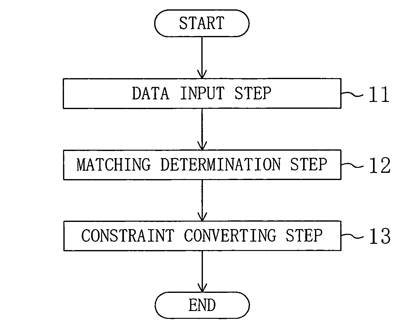
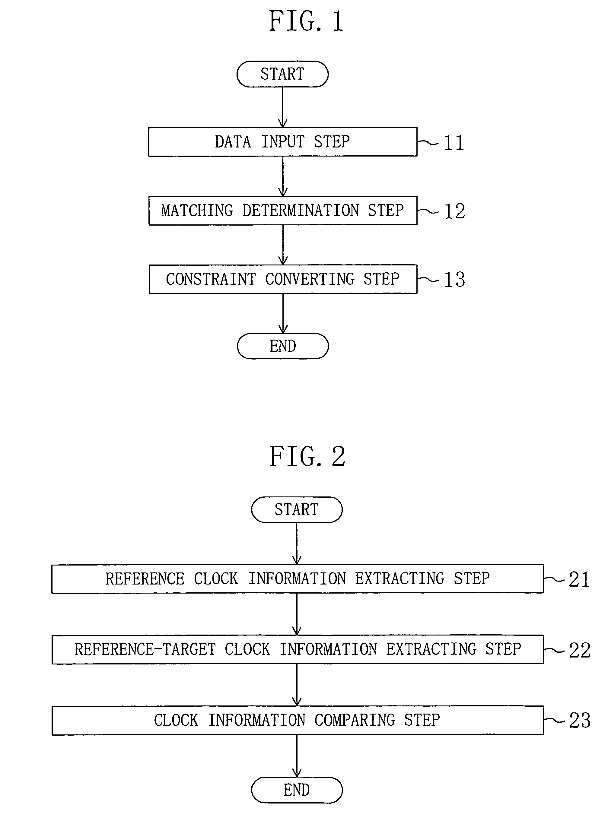
[0057]First, a first embodiment of the present invention will be described with reference to FIGS. 1, 2 and 8.
[0058]FIG. 1 is a flowchart showing process steps according to the first embodiment. In FIG. 1, step 11 is a data input step of inputting data on a logic circuit having a hierarchical structure, library data holding primitive information on the logic circuit and timing constraints on a plurality of circuit blocks at one or more lower levels of the logic circuit. Step 12 is a matching determination step of determining whether or not interface specifications of timing constraints on the lower-level blocks match each other based on the data that has been input at the data input step 11. Step 13 is a constraint converting step of converting timing constraints on the lower-level blocks after the matching determination into at least one constraint on a higher-level block. FIG. 1 for this embodiment is different from FIG. 4 for the conventional example in that the matching determin...
embodiment 2
[0066]Now, a second embodiment of the present invention will be described with reference to FIGS. 8, 9 and 10.
[0067]FIG. 9 is a flowchart showing process steps according to the second embodiment. The second embodiment is different from the first embodiment in that a matching determination step 12A of determining whether or not interface specifications match each other by comparing timing exception information (timing constraints) for changing timings of lower-level blocks to be connected to each other is provided instead of the matching determination step 12 of determining whether or not interface specifications match each other by comparing reference clock information. In this embodiment, the same reference numeral denotes the same component.
[0068]FIG. 10 shows the matching determination step 12A in detail. In FIG. 10, step 101 is a timing exception information extracting step of extracting timing exception information which has been set at an input pin or an output pin of a lower-...
embodiment 3
[0074]Now, a third embodiment of the present invention will be described with reference to FIGS. 11, 12, 13 and 14.
[0075]FIG. 11 shows a timing constraint generating method according to the third embodiment. The third embodiment shown in FIG. 11 is different from the first embodiment shown in FIG. 1 in that a matching determination step 12B of determining whether or not interface specifications match each other by determining the validity of input / output delay information is provided instead of the matching determination step 12 of determining whether or not interface specifications match each other by comparing reference clock information with each other. The input / output delay information is an output delay constraint as an external constraint on an output pin or an input delay constraint as an external constraint on an input pin.
[0076]FIG. 12 is a flowchart showing process steps of the matching determination step 12B shown in FIG. 11. Step 121 is an input / output delay information...
PUM
 Abstract
Description
Claims
Application Information
 - R&D
- Intellectual Property
- Life Sciences
- Materials
- Tech Scout
- Unparalleled Data Quality
- Higher Quality Content
- 60% Fewer Hallucinations
Browse by: Latest US Patents, China's latest patents, Technical Efficacy Thesaurus, Application Domain, Technology Topic, Popular Technical Reports.
© 2025 PatSnap. All rights reserved.Legal|Privacy policy|Modern Slavery Act Transparency Statement|Sitemap|About US| Contact US: help@patsnap.com


