Control methodology for a multi-axial wheel fatigue system

a control methodology and multi-axial wheel technology, applied in vehicle tyre testing, instruments, roads, etc., can solve problems such as complicated setup procedures, process requirements, and complicated setup procedures

Active Publication Date: 2007-08-14
MTS SYSTEMS CORPORATION
View PDF59 Cites 21 Cited by
  • Summary
  • Abstract
  • Description
  • Claims
  • Application Information

AI Technical Summary

Problems solved by technology

However, a complicated setup procedure (i.e. mapping process) is required before testing can even begin.
This setup procedure complicates testing because it takes a considerable amount of time as well as causes wear upon the test specimen.

Method used


Image

  • Control methodology for a multi-axial wheel fatigue system
  • Control methodology for a multi-axial wheel fatigue system
  • Control methodology for a multi-axial wheel fatigue system

Examples


Embodiment Construction

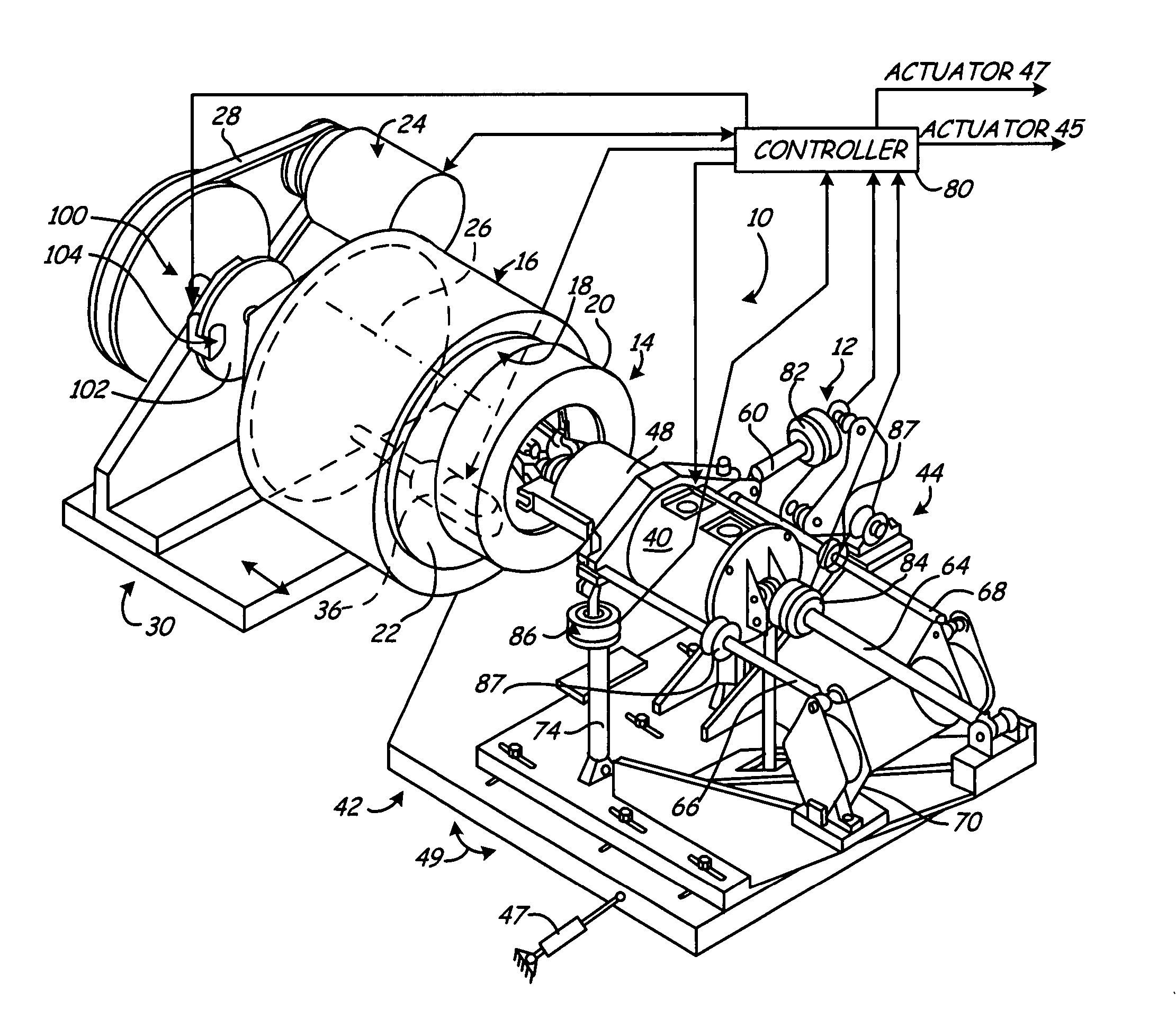
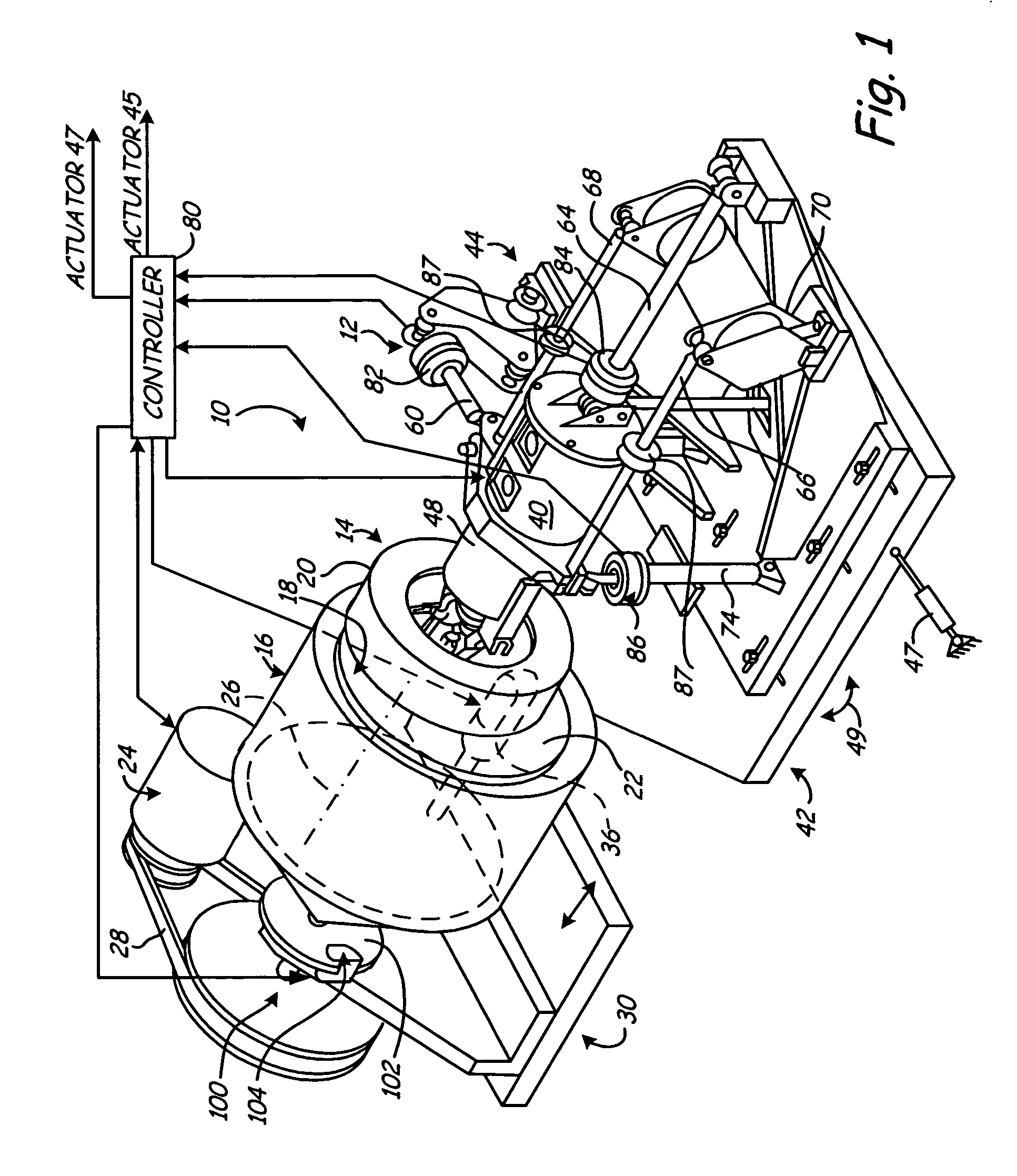
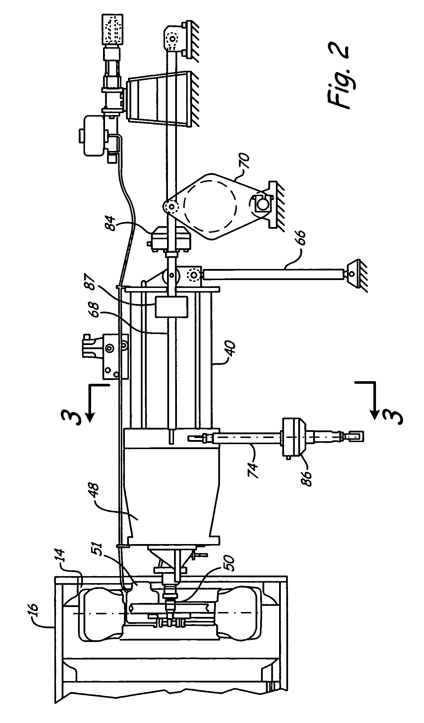
[0013]An exemplary rolling wheel testing apparatus capable of practicing the present invention is illustrated in FIG. 1 at 10. It should be noted that apparatus 10 is but one testing apparatus where those skilled in the art can appreciate aspects of the present invention can be used on other testing apparatuses, and in particular, those testing apparatuses applying loads using actuators arranged differently.

[0014]Before describing the control methodology, the testing apparatus 10 will be described. Only a brief description will be provided herein. U.S. Pat. No. 6,729,178 provides a further description and is incorporated herein by reference in its entirety. It should also be understood that the apparatus 10 is a triaxial machine that incorporates brake / drive torque. The control methodology described below can also be used with a biaxial testing apparatus that does not have brake / drive torque load inputs.

[0015]Generally, the testing apparatus 10 includes a support structure 12 that s...


PUM


Abstract

A testing system and a method for obtaining drive files for the testing system for wheel rim testing, includes providing a wheel assembly in contact with a drum surface, the wheel assembly being rotatable about an axis defining a lateral axis, and wherein a vertical axis extends through a drum surface in contact with a tire of the wheel assembly and is orthogonal to the lateral axis, and a longitudinal axis is defined orthogonal to both the lateral and vertical axes. A parameter is measured indicative of an overturning moment applied to the wheel rim about the longitudinal axis. A camber angle of the wheel rim relative to the drum surface is adjusted to obtain a desired overturning moment on the wheel rim about the longitudinal axis.

Description

CROSS-REFERENCE TO RELATED APPLICATION[0001]This application claims the benefit of U.S. Provisional Patent Application 60 / 580,566, filed Jun. 17, 2004, the content of which is hereby incorporated by reference in its entirety.BACKGROUND OF THE INVENTION[0002]The present invention relates to testing apparatuses used to test components of a motor vehicle. More particularly, the present invention relates to a testing apparatus used to test tire, wheel, spindle and / or braking components of a motor vehicle.[0003]A rolling wheel testing apparatus using the inside of a rotating drum was developed by the Fraunhofer-Institut Fur Betriebsfestigkeit and has been shown to be an effective test technique. Generally, a tire and wheel are mounted to a drive motor and is disposed within a drum where the tire engages an inside circumferential surface. Improvements have been made on the original design to simulate loading when the tire and wheel rim are mounted to a motor vehicle as the motor vehicle t...

Claims


Application Information

Patent Timeline
Patent Type & Authority Patents(United States)
IPC IPC(8): G01M17/013
CPCG01M17/022G01M17/02G01M17/013
Inventor LESKA, SR., PAUL J.CAMPBELL, CRAIG L.YOUNG, ERIC W.ACHORN, BRADLEY C.
Owner MTS SYSTEMS CORPORATION
Why Eureka
Try Eureka