Canted saw blade

a canted saw blade and cant angle technology, applied in the field of canted saw blades, can solve the problems of reduced blade strength, increased cost, and difficult to achieve higher cant angles

Inactive Publication Date: 2007-08-21
BLACK & DECKER INC
View PDF40 Cites 51 Cited by
  • Summary
  • Abstract
  • Description
  • Claims
  • Application Information

AI Technical Summary

Benefits of technology

[0006]It is a general object of the present invention to provide a positive canted saw blade while maintaining manufacturing methods and raw-material strip-widths that apply to zero-canted blades.

Problems solved by technology

Such a design provides a blade having a reduced cross sectional area near the shank end resulting in reduced blade strength.
In addition, higher cant angles are not easily achieved due to the length of the blade.
Such an arrangement can require 10-15% wider material strip which drives up cost.

Method used


Image

  • Canted saw blade
  • Canted saw blade
  • Canted saw blade

Examples


Embodiment Construction

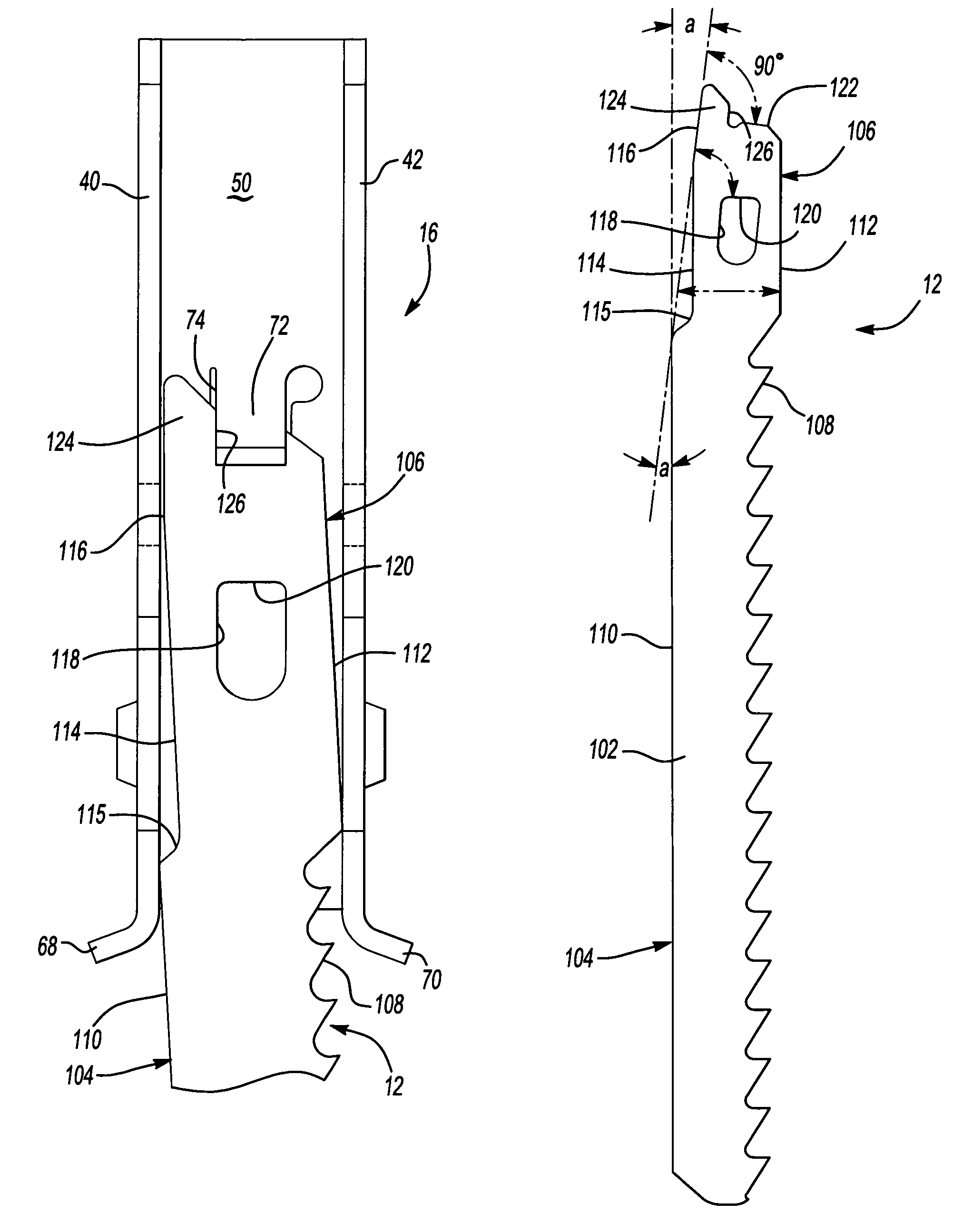
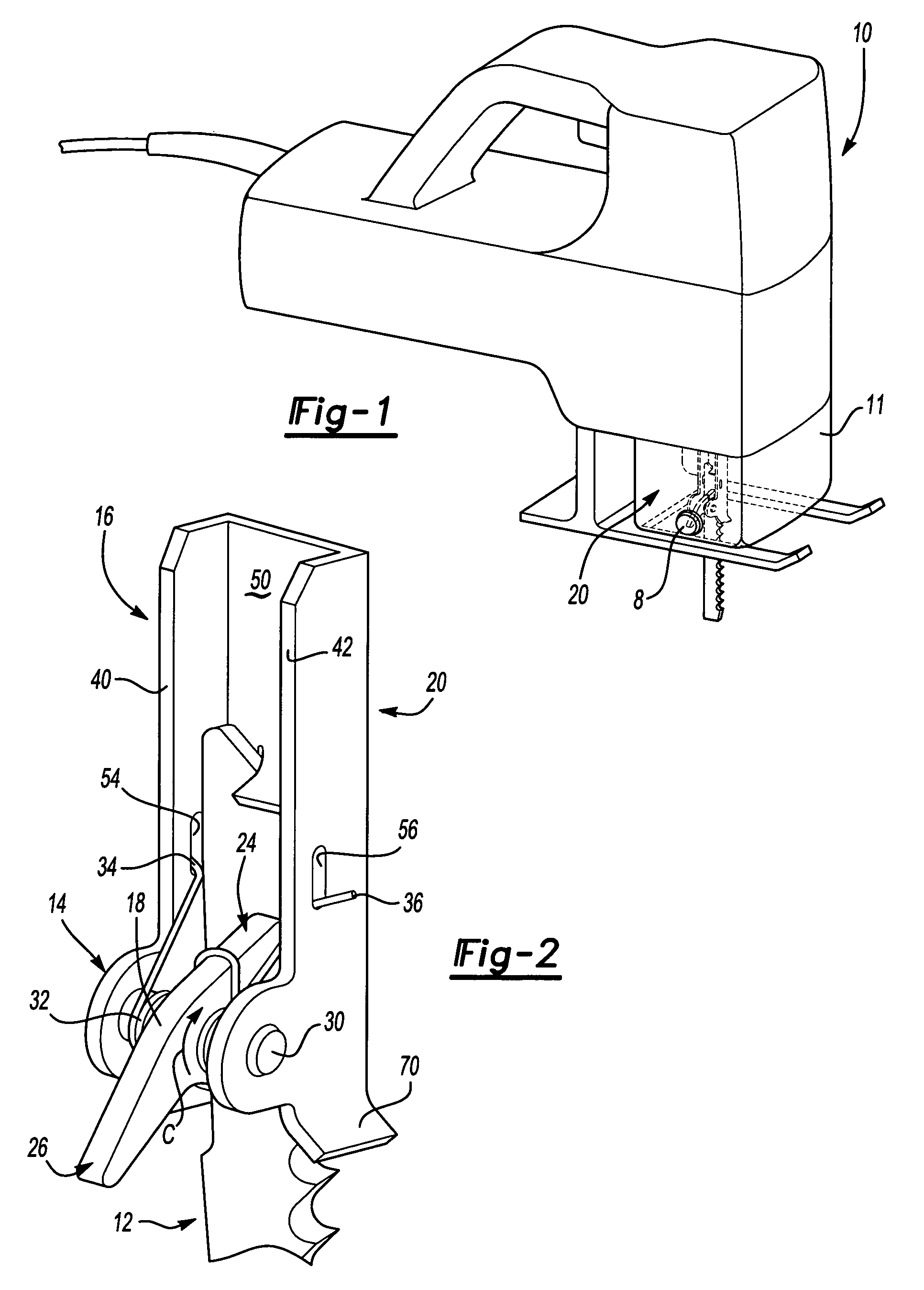
[0020]With initial reference to the perspective view of FIG. 1, a retaining mechanism or clamp device 20 according to the teachings of the present invention is illustrated within a housing 11. The housing 11 includes push button 8 which is operable to disengage the clamp device 20. The clamp device 20 is shown operatively interconnected to a conventional jig saw 10 and is configured to securely retain a plurality of saw blades having a variety of thicknesses. For example, as shown in FIG. 5, the clamp device 20 is configured to securely retain a first or second blade 12, 12′ with different thicknesses.

[0021]For exemplary purposes, blades 12 and 12′ are provided in the illustrations. Blade 12 has a thickness A of 0.035 inches (0.89 mm) and blade 12′ has a thickness A′ of 0.05 inches (1.27 mm). Blades 12 and 12′ generally fit the “thin” and “thick” blade categories respectively.

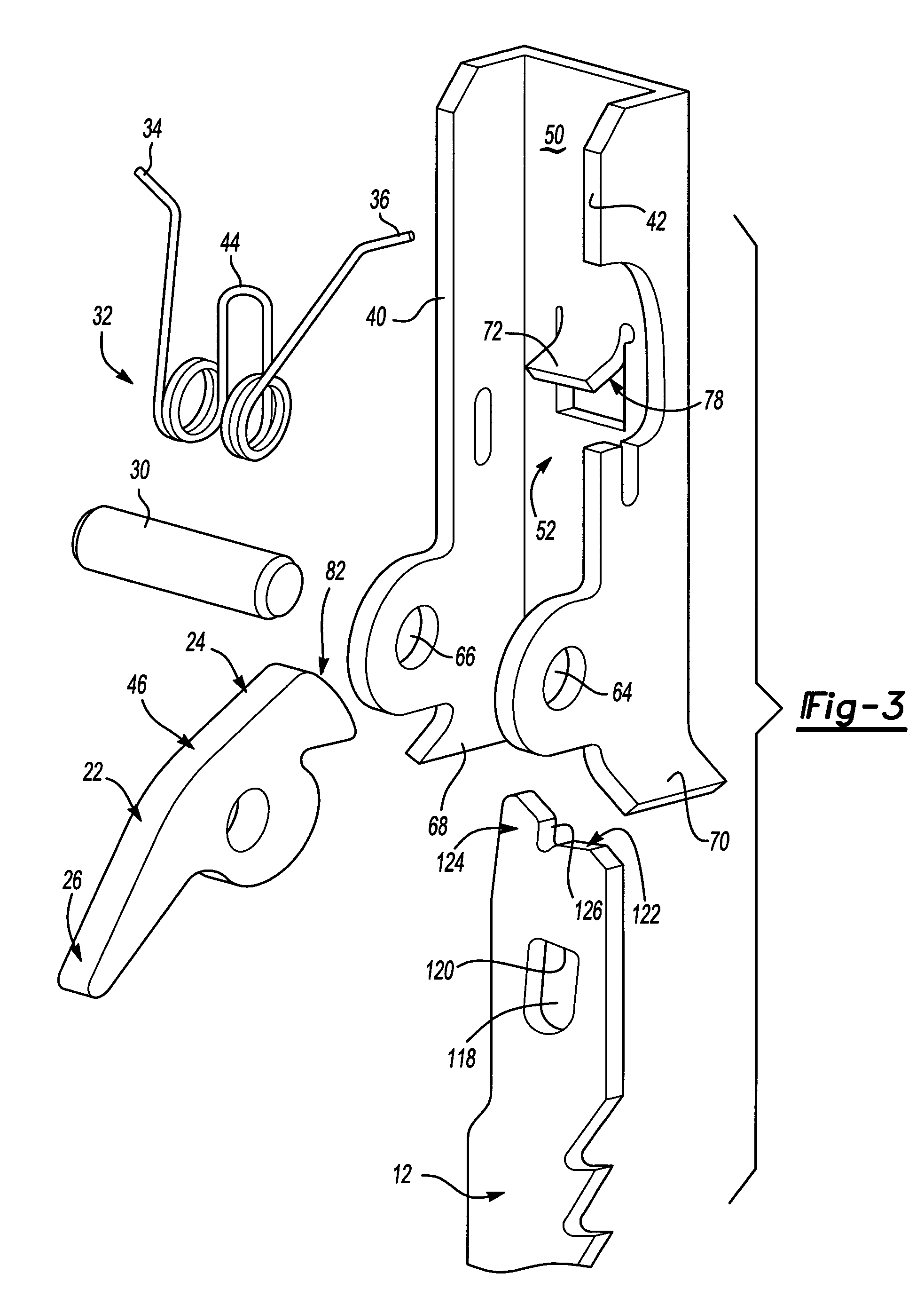
[0022]With continued reference to FIG. 1, and additional reference to FIGS. 2 and 3 wherein the housing 11 a...


PUM

PropertyMeasurementUnit
angleaaaaaaaaaa
angleaaaaaaaaaa
thicknessaaaaaaaaaa

Abstract

A saw blade incorporates an integrated cant angle. The saw blade includes a cutting portion having a toothed edge and opposite edge. The toothed edge defines a cutting plane. A shank portion extends from the cutting portion and is laterally offset from the opposite edge of the cutting portion defining a step thereat. The shank includes an end portion including a mounting edge, the mounting edge and step define a mounting plane which is angularly offset from the cutting plane.

Description

FIELD OF THE INVENTION[0001]The present invention relates generally to saw blades, and more particularly to a saw blade having an integrated cant angle.BACKGROUND[0002]A reciprocating saw blade may include features that provide increased cutting speed. For example, hook angle, kerf, teeth per inch and cant-angle may be adjusted to allow faster cutting time. The first three features allow a certain variation without incurring additional manufacturing costs. However, to include a non-zero cant angle, additional processing steps or process types must be used.[0003]For example, a first conventional design includes a canted blade including a toothed edge tapering toward the shank end. Such a design provides a blade having a reduced cross sectional area near the shank end resulting in reduced blade strength. In addition, higher cant angles are not easily achieved due to the length of the blade.[0004]A second conventional design includes a canted blade including a shank extending at a pred...

Claims


Application Information

Patent Timeline
Patent Type & Authority Patents(United States)
IPC IPC(8): B23D51/10B23D61/12B27B19/02
CPCB23D51/10B23D61/128B23D61/123Y10T279/17769Y10T83/9319Y10T83/9454Y10T83/9481
Inventor WHEELER, THOMAS J.ACHTERBERG, NICHOLAS E.GAFFNEY, THOMAS M.
Owner BLACK & DECKER INC
Why Eureka
Try Eureka