Conveyorized oven with moisture laden air impingement and method

Inactive Publication Date: 2007-08-21
ENODIS
View PDF28 Cites 46 Cited by
  • Summary
  • Abstract
  • Description
  • Claims
  • Application Information

AI Technical Summary

Benefits of technology

[0012]Preferably, the air impingement assembly comprises one or more jet fingers disposed above and/or below the conveyor. In some embodiments of the present invention the

Problems solved by technology

The separate steam system ad

Method used


Image

  • Conveyorized oven with moisture laden air impingement and method
  • Conveyorized oven with moisture laden air impingement and method
  • Conveyorized oven with moisture laden air impingement and method

Examples


Embodiment Construction

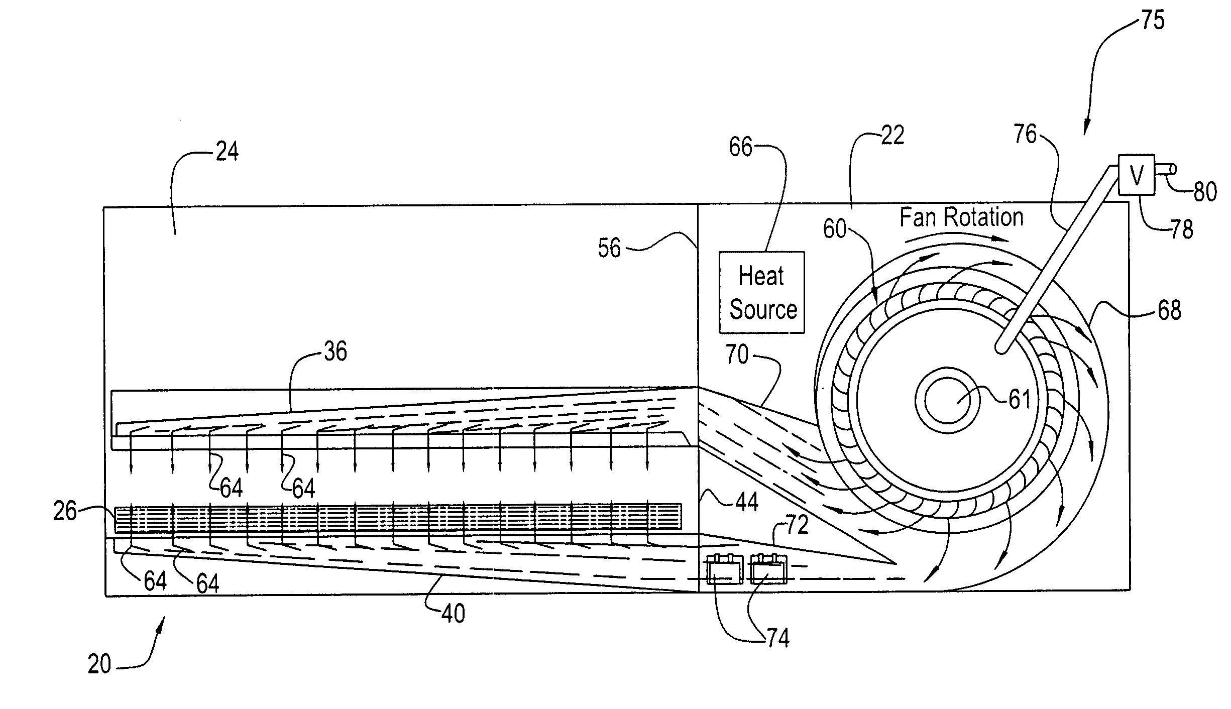
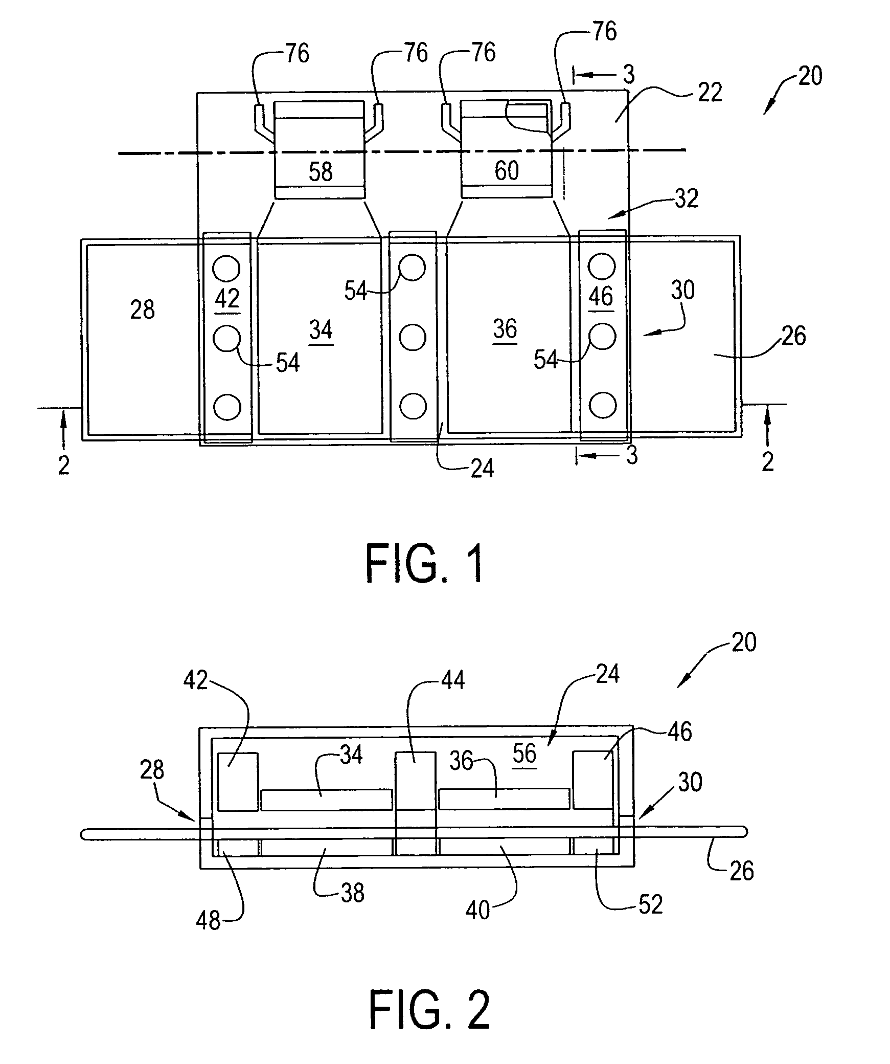
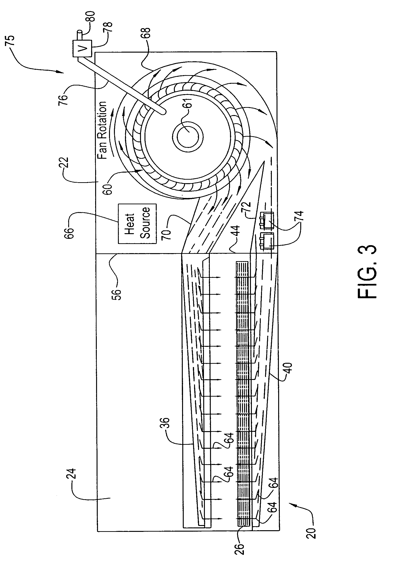
[0027]Referring to FIGS. 1-3, a conveyor oven 20 of the present invention includes a heating chamber 22, an oven chamber 24 and a conveyor 26. Conveyor 26 is disposed to convey food products, such as pizza, through oven chamber 24 by entering an entry port 28 and exiting an exit port 30 of oven chamber 24. That is, conveyor 26 carries food products in the direction of left to right in FIGS. 1 and 2. Conveyor 26 may be moved or rotated by any suitable conveyor motion assembly (not shown), known presently or in the future. It will be apparent to those skilled in the art that the conveyor direction can be reversed simply by changing the direction of rotation of a drive motor of the conveyor motion assembly.

[0028]An impingement air duct assembly 32 includes an upper impingement finger 34, an upper impingement finger 36, a lower impingement finger 38, a lower impingement finger 40 and return ducts 42, 46, 48 and 52. Upper impingement finger 34 is disposed in oven chamber 24 above conveyo...


PUM


Abstract

A conveyor oven having a heating chamber and an oven chamber. A conveyor is disposed in the oven chamber to convey food products between an entry port and an exit port. An air impingement assembly is disposed to provide jets of impingement air toward the food product. A fan blower, a heater and a moisture delivery device are arranged to provide heat and moisture to an airflow to the air impingement assembly so that the jets of air are heated and laden with moisture and provide as a blanket-like mixture of air and moisture at the surface of the food product.

Description

[0001]This application claims the benefit of U.S. Provisional application 60 / 368,024, filed on Mar. 27, 2002 and U.S. Provisional application 60 / 383,978, filed on May 29, 2002, the entire contents of each being incorporated herein by reference.FIELD OF THE INVENTION[0002]This invention relates to a conveyor oven and method of operating a conveyor oven. In particular, the invention relates to a conveyor oven and method that cooks food products by heated impingement air.BACKGROUND OF THE INVENTION[0003]Conveyor ovens that use impingement air are known for the cooking of various products, including bakery products, pizza and various other food products. Typical conveyor ovens using impingement air are described in U.S. Pat. Nos. 4,701,340, 4,873,107 and 5,832,812. U.S. Pat. No. 4,701,340 discloses a conveyor oven that includes three cooking zones serially arranged along the conveyor path. The two end zones apply jets of heated impingement air to food products carried on the conveyor. T...

Claims


Application Information

Patent Timeline
IPC IPC(8): A21B1/26A21B1/24A21B1/42A21B3/04A23L3/18A23L3/365A23L5/10A47J39/00F24C15/32
CPCA21B1/245A21B1/48A21B3/04A23L1/0135A23L3/18A23L3/185A23L3/365A23L5/17
Inventor JONES, DOUGLAS S.MOLLOY, PAUL RDAY, JR., WILLIAM J.
Owner ENODIS
Why Eureka
Try Eureka