Illuminated foot-switch

a control switch and foot technology, applied in the field of foot-activated control switches, can solve the problems of difficulty for operators to have one hand free to manipulate and control hand-activated switches, limited control systems, and cumbersome dexterity of operators with respect to their

Inactive Publication Date: 2007-08-21
COVIDIEN AG
View PDF30 Cites 33 Cited by
  • Summary
  • Abstract
  • Description
  • Claims
  • Application Information

AI Technical Summary

Problems solved by technology

However, a hand-held control unit requires that the operator interrupt the on-going medical / surgical procedure in order to actuate the various functions of the multi-functional device as needed.
As may be appreciated, it is undesirable and often difficult for the operator to have one hand free to manipulate and control hand-actuated switches.
While foot-operated control systems have been suitable for a variety of different apparatus, such control systems have generally been limited to the types of surgical procedures in which the foot operated control system can be utilized.
The dexterity of an operator with respect to his / her feet is much more cumbersome compared to hand dexterity, especially when the operator is wearing shoes, as will normally be the case.
Moreover, during many surgical procedures, the operating rooms are typically dark.
Should the operator errantly place his / her foot on the incorrect or undesired actuation pedal, the operator may accidentally actuate the incorrect function on the multi-function device which may prove traumatic.
However, in a darkened operating room, the operator may still not be able to discern which actuation pedal to actuate even if the operator is looking in the direction of the foot control system.

Method used


Image

  • Illuminated foot-switch
  • Illuminated foot-switch
  • Illuminated foot-switch

Examples


Embodiment Construction

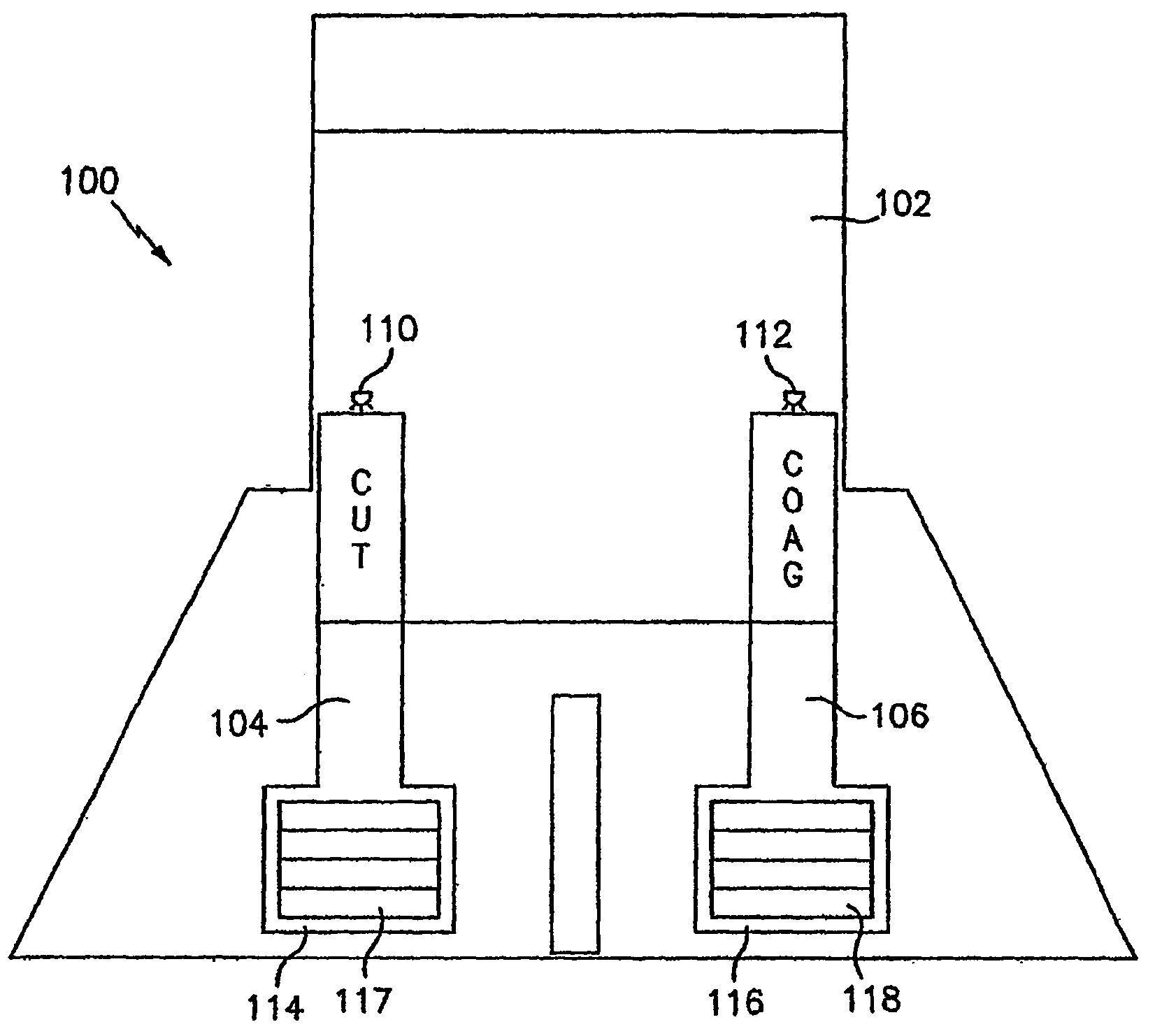
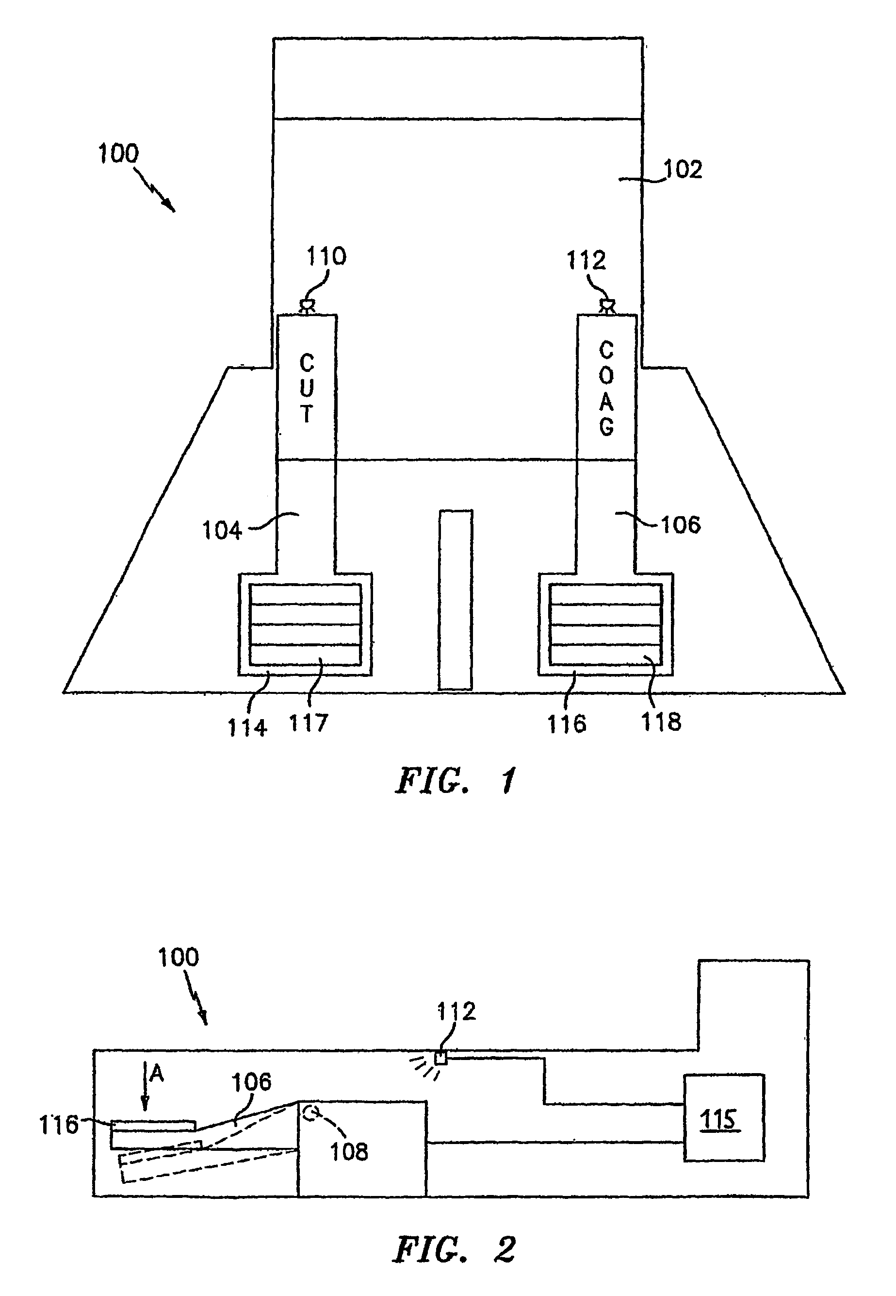
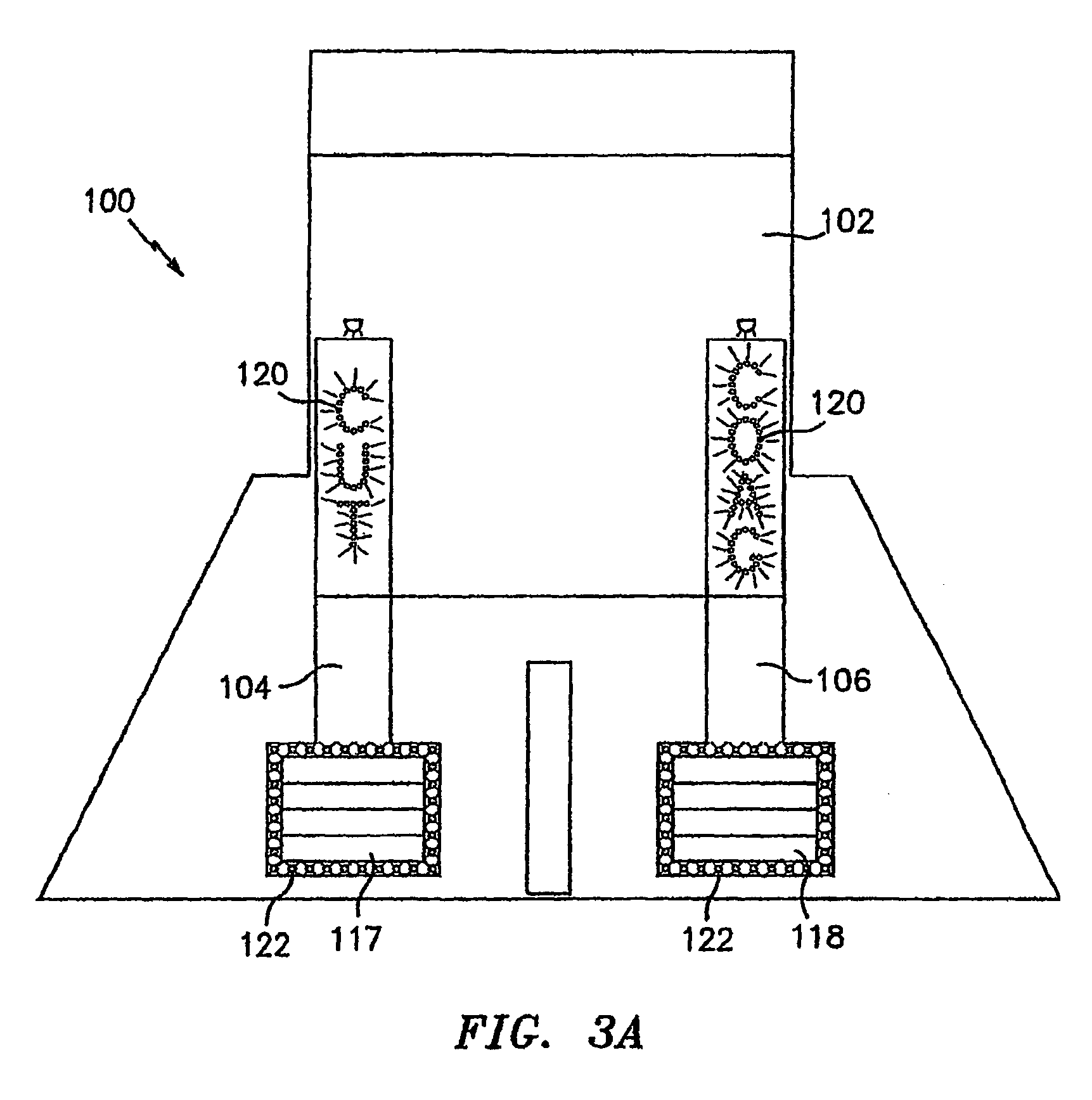
[0028]Preferred embodiments of the presently disclosed illuminated foot-activated control switch will now be described in detail with reference to the drawing figures wherein like reference numerals identify similar or identical elements. The illuminated foot-activated control switch as shown herein is described as actuating an electrosurgical instrument which can perform many different functions, e.g., cutting (i.e., referred to as “CUT” in the figures), coagulating (i.e., referred to as “COAG” in the figures) and sealing (i.e., “SEAL” in the figures). While only certain functions are shown in the figures it is within the scope of the present disclosure that any electrosurgical instrument can be operatively coupled to the illuminated foot-activated control switch and be actuated by a corresponding control switch.

[0029]Referring now in detail to FIGS. 1 and 2, an illuminated foot-activated control switch is shown in accordance with the present disclosure and is generally identified ...


PUM


Abstract

A control system for an electrosurgical instrument includes a housing selectively positionable relative to an operating theater with the housing being coupled to an electrosurgical energy source. The system also includes at least one foot-activatable pedal operatively engaged with the housing which has indicia identifying the function of the pedal disposed thereon. Illuminating means are also included with the system which illuminating means are designed to illuminate at least a portion of the pedal which, in turn illuminates the indicia.

Description

CROSS-REFERENCE TO RELATED APPLICATIONS[0001]The present application claims the benefit of and priority to International Application Serial No. PCT / US03 / 17126, filed on May 29, 2003, which claims the benefit of and priority to U.S. Provisional Patent Application No. 60 / 388,658 filed on Jun. 11, 2002, the entire contents of which are incorporated herein by reference.BACKGROUND[0002]1. Technical Field[0003]The present disclosure relates to a foot-activated control switch and, more particularly, to an illuminated foot-activated control switch for use during a surgical procedure and, even more particularly, to an illuminated foot-activated control switch for use in a darkened operating room during a surgical procedure.[0004]2. Background of Related Art[0005]Many surgical devices today are configured to perform a variety of different selectable functions or operations. Such multi-function devices are typically equipped with some kind of control mechanism to allow an operator to select an...

Claims


Application Information

Patent Timeline
Patent Type & Authority Patents(United States)
IPC IPC(8): H01H9/20H01H3/14A61B19/00A61B17/00A61B18/00A61B18/12H01H9/16H01H9/18
CPCH01H3/14H01H9/182A61B18/12A61B2017/00973H01H9/181
Inventor BLAHA, DEREK M.GREGG, WILLIAM N.
Owner COVIDIEN AG
Why Eureka
Try Eureka