
Electronic pedometer

a pedometer and electronic technology, applied in the field of electronic pedometers, can solve the problems of increasing the period required to drive the circuit, the inability to measure the number of steps in a case, and the inability to use electronic pedometers of this type for watch-type pedometers

Inactive Publication Date: 2007-08-28
SEIKO INSTR INC
View PDF15 Cites 18 Cited by
  • Summary
  • Abstract
  • Description
  • Claims
  • Application Information

AI Technical Summary

Benefits of technology

Enables miniaturization and accurate step counting even when arms are not swung, maintaining the watch-type form factor and reducing circuit complexity.

Problems solved by technology

However, there is encountered a problem that the number of steps cannot be measured in a case where a user walks with his / her arm being fixed to a predetermined position (e.g., at the ear) without swinging his / her arms, for example, in a case where the user walks while he / she communicates with someone using his / her mobile telephone.
However, there is encountered a problem in that a volume increases and circuits for amplifying signals from the sensors are required to be doubled in number because the two sensors are used, or when the electronic pedometer is driven in a time division manner in order to prevent such a situation, a time period required to drive the circuits increases, and hence the electronic pedometer of this type is unsuitable for the watch type pedometer.

Method used


Image

  • Electronic pedometer
  • Electronic pedometer
  • Electronic pedometer

Examples


Embodiment Construction

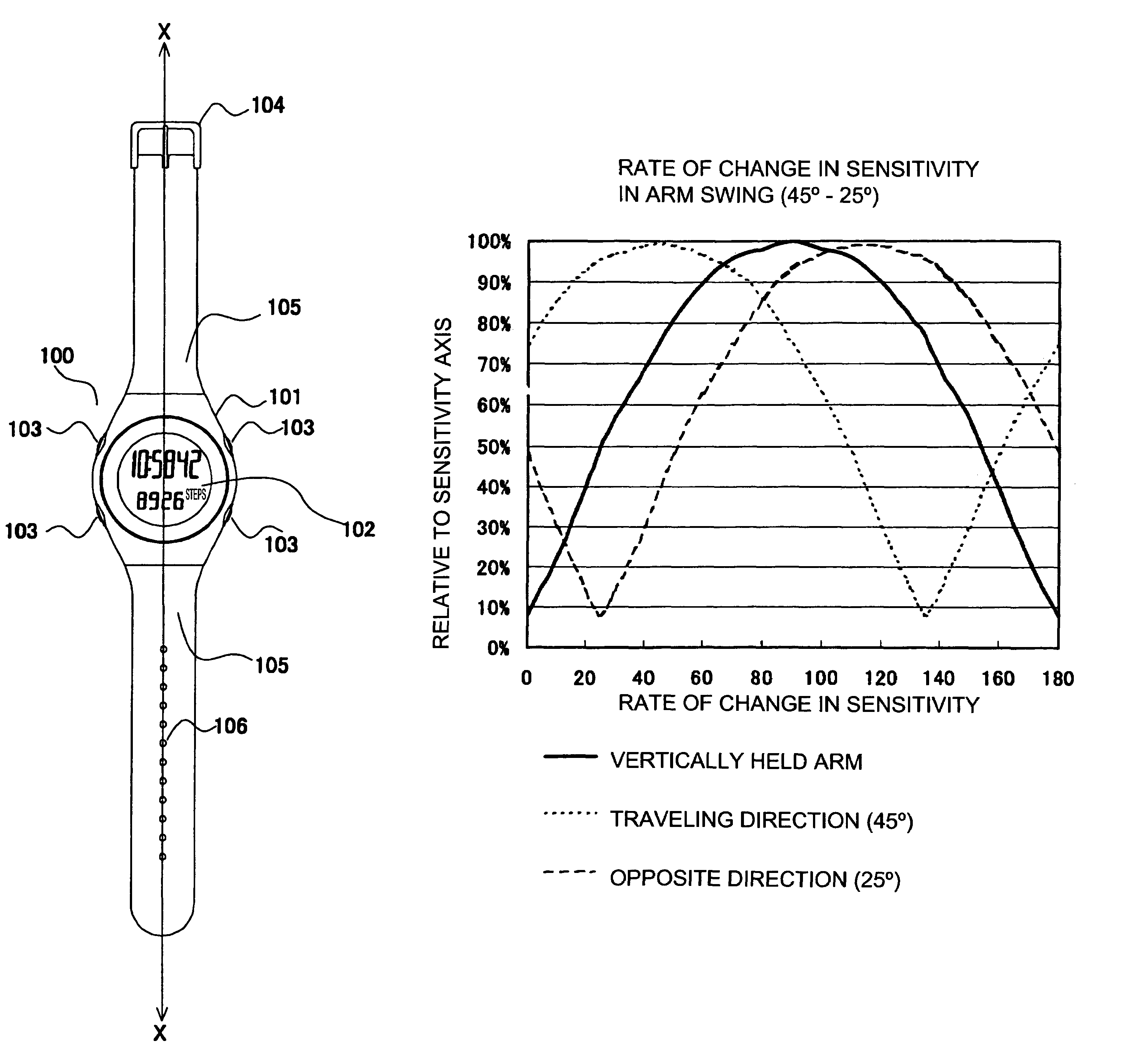
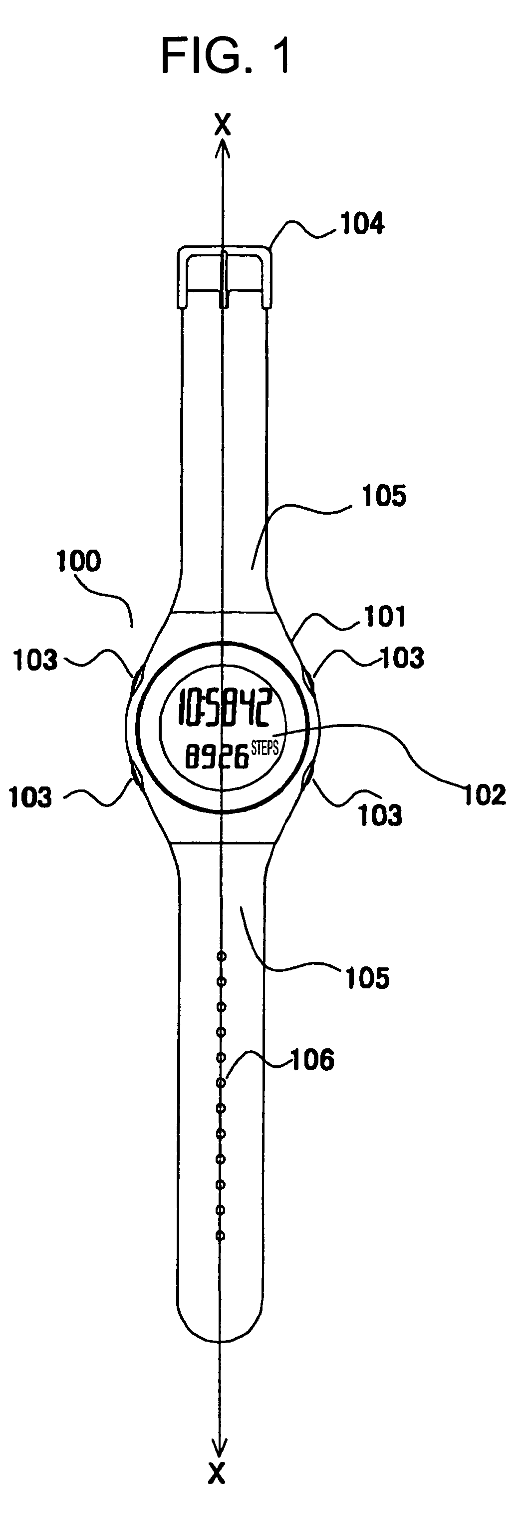
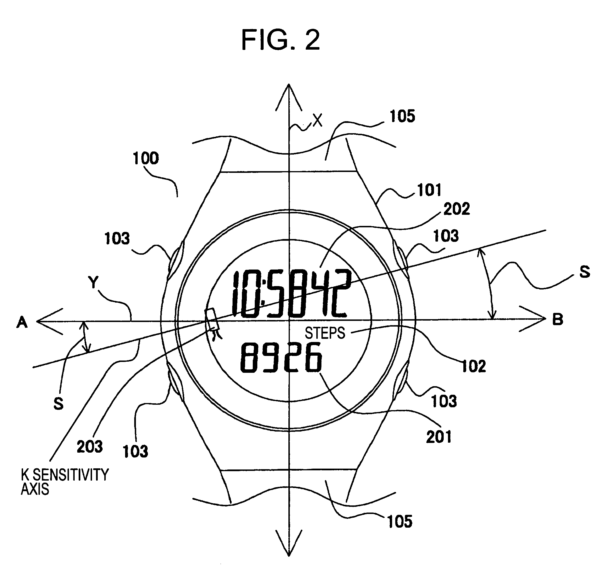
[0032]An electronic pedometer according to an embodiment mode of the present invention is a watch type electronic pedometer which is used by being worn on a wrist of a user. The watch type electronic pedometer has: an acceleration sensor as a walk sensor for detecting a walk of a user to output a walk signal corresponding to the walk; calculation means for calculating the number of steps of the user based on the walk signal; and a belt with which at least the acceleration sensor is worn on a wrist of the user, and is used at least by wearing the acceleration sensor on the wrist of the user using the belt. The electronic pedometer according to this embodiment mode will hereinafter be described with reference to the drawings.

[0033]FIG. 1 is a front view showing an external appearance of an electronic pedometer according to an embodiment mode of the present invention, and shows an electronic pedometer for a left wrist which is used by being worn on a left wrist of a user. In addition, ...


PUM


Abstract

An electronic pedometer has a walk sensor that detects a walking movement of a user and outputs a walk signal corresponding to the walking movement. The walk sensor has a sensitivity axis along which a detection sensitivity of the walking movement by the walk sensor becomes a maximum. A calculation circuit calculates a number of walking steps of the user in accordance with the walk signal. A strap mounts the walk sensor on a part of the user's body so that the sensitivity axis of the walk sensor is located within a range of 30 degrees or less in either a clockwise or counterclockwise direction from an axis disposed at 90 degrees with respect to a longitudinal direction of the strap.

Description

BACKGROUND OF THE INVENTION[0001]1. Field of the Invention[0002]The present invention relates to an electronic pedometer for measuring the number of steps by detecting a walk of a person or the like.[0003]2. Description of the Prior Art[0004]Heretofore, there has been developed an electronic pedometer for measuring the number of steps of a user by detecting a walk of the user using a walk sensor.[0005]A watch type pedometer which is used by being worn on a wrist of a user like a watch has been developed as the electronic pedometer (refer to Patent Document 1 for example).[0006]With the above conventional watch type electronic pedometer, since a pendulum sensor is used, the number of steps can be measured in a normal walk in which a user walks while he / she naturally swings his / her arms. However, there is encountered a problem that the number of steps cannot be measured in a case where a user walks with his / her arm being fixed to a predetermined position (e.g., at the ear) without swi...

Claims


Application Information

Patent Timeline
Patent Type & Authority Patents(United States)
IPC IPC(8): G06F15/00A63B71/06G01B21/02G01C22/00G01P3/50G01P15/00G06M3/00G06M7/00
CPCG01P3/50G01P15/00A63B71/06G01C22/006A63B2071/0663G06M7/00
Inventor SUGAI, YOSHINORI
Owner SEIKO INSTR INC
Learn More