
Electronically actuated locking differential

a technology of locking differential and electric actuator, which is applied in the direction of differential gearings, non-mechanical controls, belts/chains/gearrings, etc., can solve the problems of limiting the performance capability of locking differential, affecting the operation of the locking mechanism, and affecting the operation of the devi

Active Publication Date: 2007-09-04
EATON INTELLIGENT POWER LTD
View PDF5 Cites 61 Cited by
  • Summary
  • Abstract
  • Description
  • Claims
  • Application Information

AI Technical Summary

Benefits of technology

[0008]It is a related object of the present invention to provide such an improved locking differential which utilizes, more effectively than in the prior art, the available space in the differential to accommodate both the locking mechanism and the actuator mechanism.

Problems solved by technology

Although electrically actuated locking differentials made in accordance with the teachings of the above-incorporated patents are now in commercial production, and are performing in a satisfactory manner, the design configuration illustrated and described in the above-incorporated patents has one inherent characteristic which can limit the performance capability of the locking differential.
Furthermore, ball ramp devices inherently have a relatively small axial displacement, as the device “ramps up”, and that can represent a disadvantage in a locking differential, as will be described subsequently.
Furthermore, the travel of the locking mechanism is, in the devices of the above-incorporated patents, limited by the axial travel of the ball ramp device, i.e., by the axial travel of the “inner ramp plate” disposed adjacent the differential case.
It has now also become understood that in the devices of the above-incorporated patents, the travel of the locking mechanism, and therefore, the torque capacity of the locking mechanism is further limited by the arrangement wherein the locking mechanism is associated with the side gear adjacent the actuator (the electromagnetic coil and ball ramp device), such that there is within the “package” a limited amount of space for the locking mechanism to achieve its “travel”.
The requirement for a biasing spring arrangement which is able to move the locking mechanism a distance equal to the required “travel” of the locking mechanism makes it much more difficult to package the locking mechanism, especially in the case of those devices in which the locking mechanism is on the end of the device immediately adjacent the actuator.

Method used


Image

  • Electronically actuated locking differential
  • Electronically actuated locking differential
  • Electronically actuated locking differential

Examples


Embodiment Construction

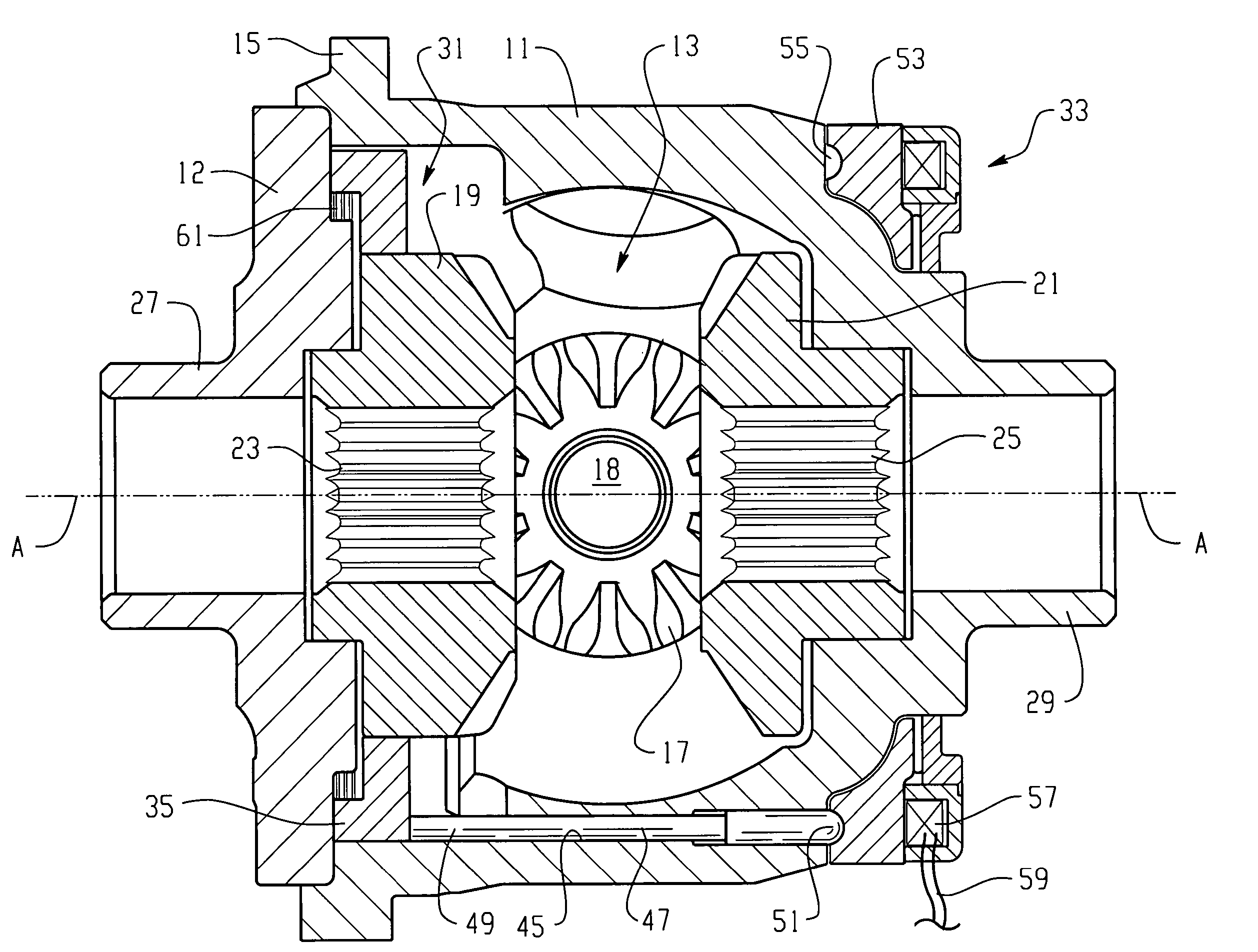
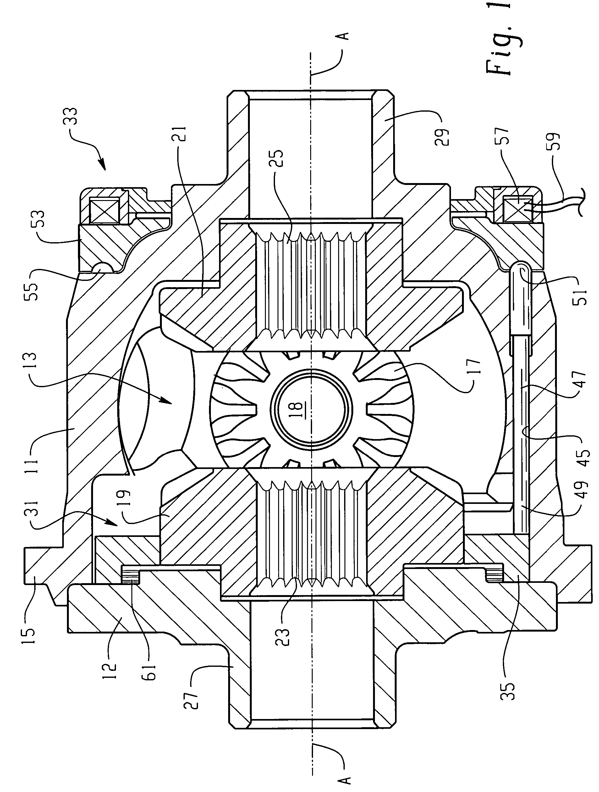
[0016]Referring now to the drawings, which are not intended to limit the invention, FIG. 1 is an axial cross-section of a locking differential including the present invention. The construction and operation of locking differentials of the general type illustrated in FIG. 1 may be better understood by reference to the above-incorporated patents.

[0017]The locking differential shown in FIG. 1 includes a gear case 11 and an end cap 12, which may be attached to the gear case 11 by any suitable means, such as a plurality of bolts (not shown herein). The gear case 11 and the end cap 12 cooperate to define a gear chamber, generally designated 13. Torque input to the locking differential is typically by means of an input ring gear (also not shown herein) which may be attached to a flange 15 (shown only fragmentarily in FIG. 1, but more fully in FIGS. 3 and 4).

[0018]Disposed within the gear chamber 13 is a differential gear set including a pair of input pinion gears 17 (only one of which is s...


PUM


Abstract

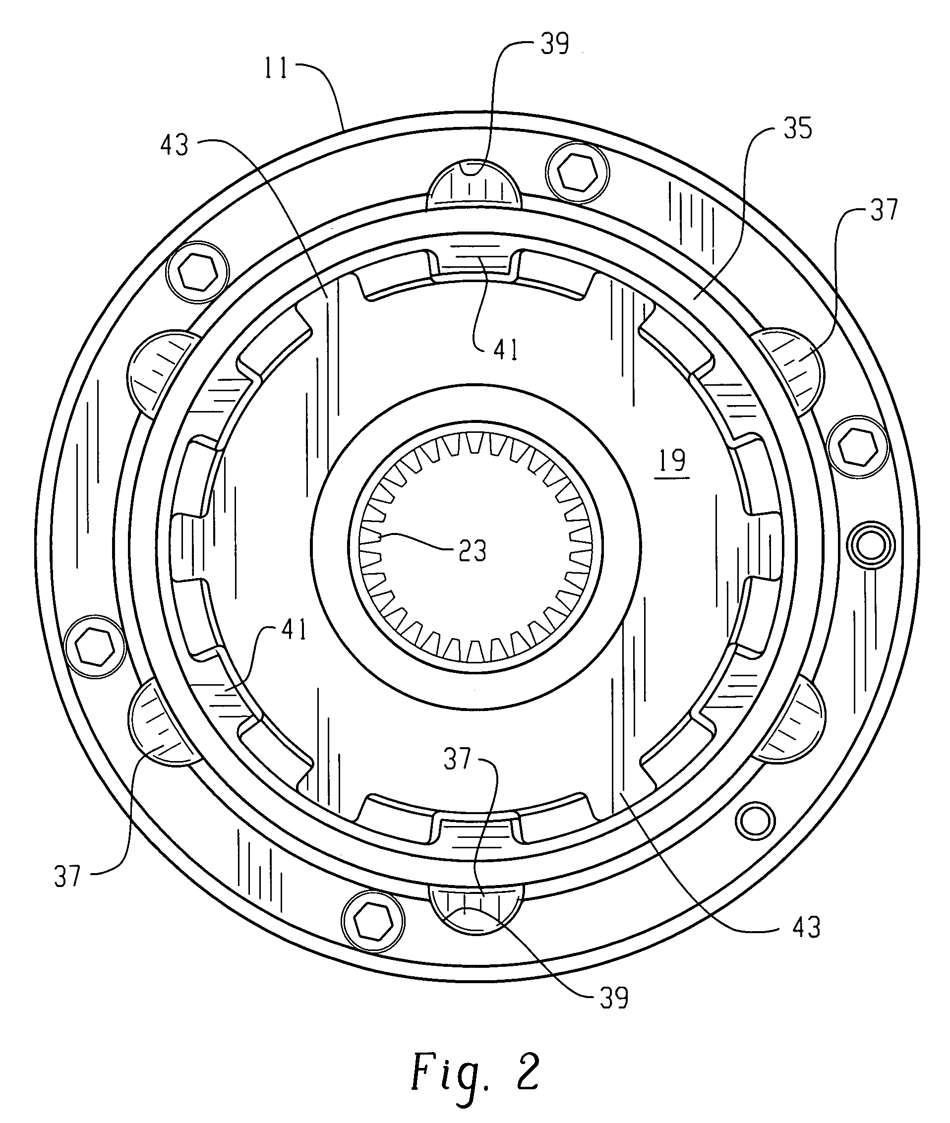
A locking differential having a collar member (35) fixed to rotate with the gear case (11), but free to move axially, and cooperating with a first sidegear (19) to define interdigitated lock members (41,43) operable, when the collar member is locked (FIG. 1), to prevent rotation of the first sidegear relative to the gear case (11). A spring (61) is disposed between the collar member and the gear case, to bias the collar member toward unlocked (FIG. 3). A plurality of actuation members (47) is provided, each having a first end (49) in engagement with the collar member, and a second end (51) in engagement with a ramp plate (53). When the actuating means is in the actuated condition, the ramp plate rotates relative to the gear case, and the actuation members ramp-up on the ramp plate and move the collar member from unlocked to locked.

Description

BACKGROUND OF THE DISCLOSURE[0001]The present invention relates to traction modifying differential devices, and more particularly, to such devices of the type in which the differential gearing can be “locked” in response to an input signal, such as an electrical input signal.[0002]Traction modifying locking differentials of the type to which the present invention relates typically include a gear case defining a gear chamber, and disposed therein, a differential gear set including at least one input pinion gear and a pair of output side gears. Typically, such a “locking differential” includes some sort of locking mechanism to prevent rotation of one of the side gears relative to the gear case, the engagement of the locking mechanism being initiated by some sort of actuator. By way of example only, the actuator could include a ball ramp mechanism in which rotation of a ramp plate is retarded relative to the gear case, thus initiating ramping, in response to a signal being transmitted ...

Claims


Application Information

Patent Timeline
Patent Type & Authority Patents(United States)
IPC IPC(8): F16H48/20
CPCF16H48/08F16H48/24F16H48/295F16H48/34F16H48/30F16H2048/346F16H2048/204E05B47/00
Inventor FOX, MATTHEW G.
Owner EATON INTELLIGENT POWER LTD
Learn More