Horizontally oriented gas separator

a horizontal orientation and separator technology, applied in the field of well pumps, can solve the problems of both types of pumps becoming less efficien

Active Publication Date: 2007-09-18
BAKER HUGHES INC
View PDF7 Cites 45 Cited by
  • Summary
  • Abstract
  • Description
  • Claims
  • Application Information

AI Technical Summary

Benefits of technology

[0005]An intake apparatus for submersible well pump restricts the flow of gas when the well pump is oriented horizontally. The inlet device has a tubular housing that mounts to an intake of the pump. The housing has a sidewall with a plurality of apertures. A sleeve is mounted within the housing for rotation relative to the housing. The sleeve has an open downstream end that registers with an open downstream end of the housing. A row of slots is formed the sleeve. The slots are axially spaced apart from each other. At least one weight causes the sleeve to rotate to a position with the row of slots at the bottom of the sleeve when the pump is oriented horizontally.

Problems solved by technology

Both types of pumps become less efficient when significant amounts of gas from the well fluid flow into the intakes.

Method used


Image

  • Horizontally oriented gas separator
  • Horizontally oriented gas separator
  • Horizontally oriented gas separator

Examples


Embodiment Construction

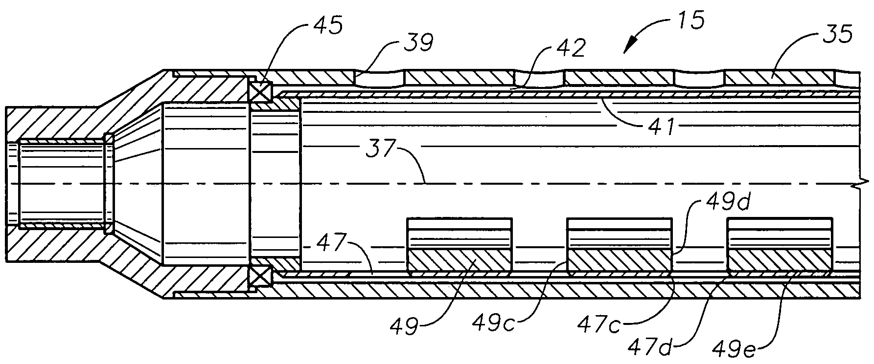
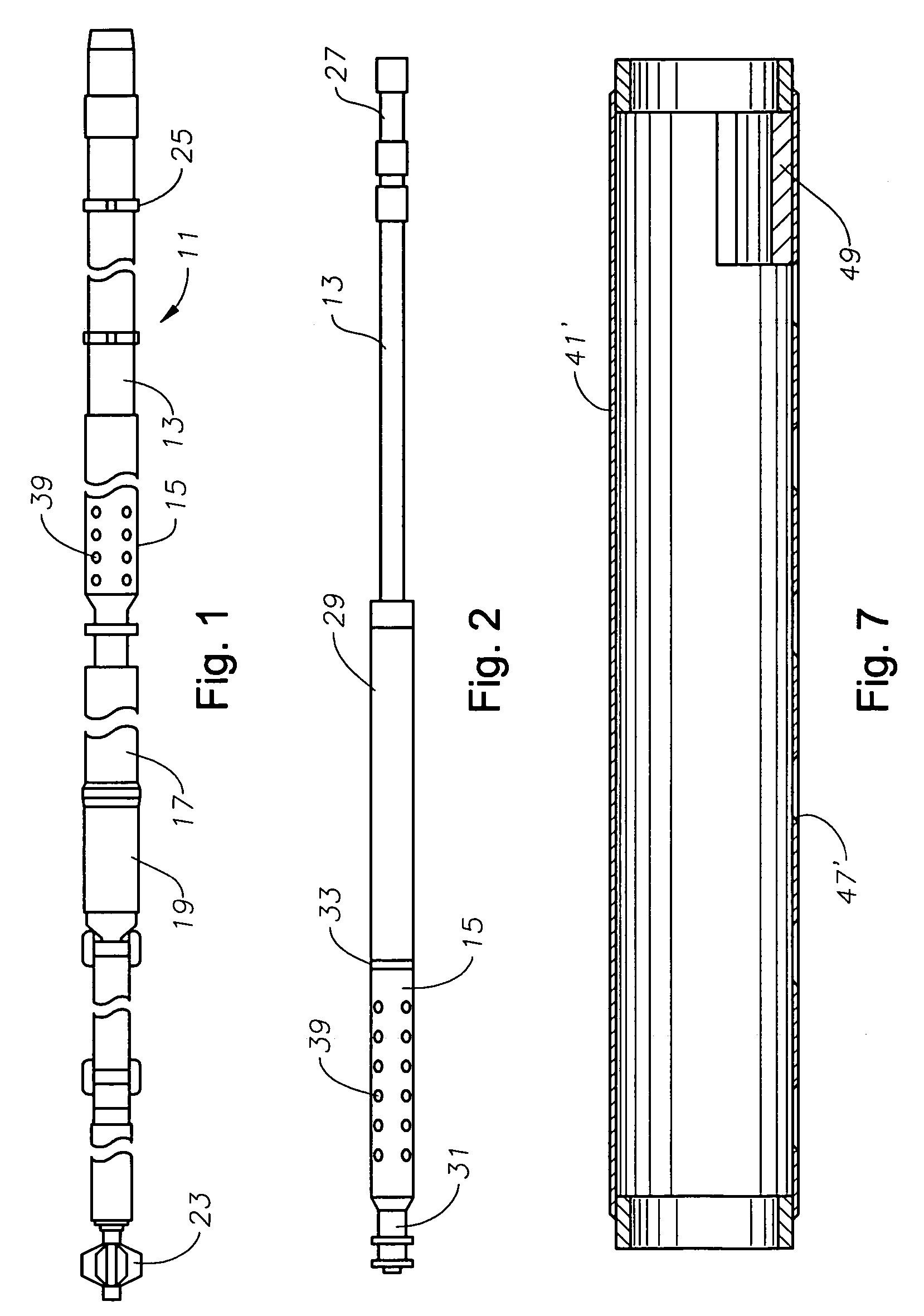
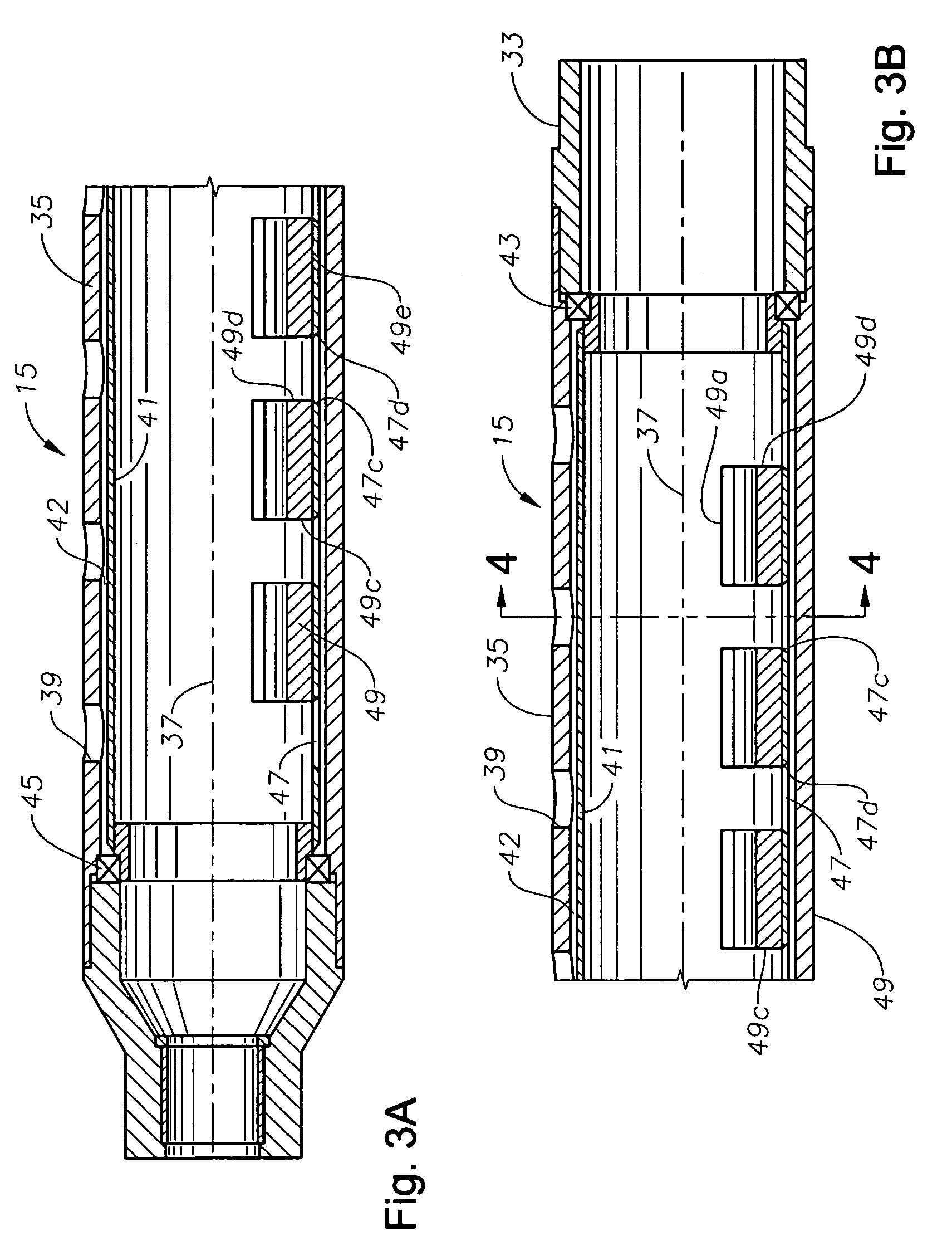
[0014]Referring to FIG. 1, pump assembly 11 is particularly configured for being used within a well having a horizontal section. Well pump assembly 11 has a pump 13 that in this embodiment comprises a progressing cavity pump, but it could be another type. Pump 13 has a rotor with a helical contour that is rotated within an elastomeric stator having a double helical passage. An intake section 15 secures to the upstream end of pump 13 for delivering well fluid to pump 13. A seal section 17 is located at the upstream end of intake section 15. A gear box 19 secures between seal section 17 and an electrical motor 21. Motor 21 drives a shaft assembly that extends from gear box 19 through seal section 17 and intake section 15 to the rotor of pump 13. Centralizers 23, 25 are located at opposite ends of pump assembly 11. Additional centralizers may be located between centralizers 23, 25, as shown.

[0015]Referring to FIG. 2, the housing of pump 13 is shown connected to production tubing 27 tha...


PUM


Abstract

A gas restrictor for an intake of a horizontally oriented submersible well pump has a tubular housing and a number of apertures. A sleeve is mounted within the housing for rotation relative to the housing. The sleeve has an axially extending row of slots. At least one weight in the sleeve causes the sleeve to rotate to a position with the row of slots at the bottom of the sleeve while the well pump is oriented horizontally. The slots and apertures are arranged so that regardless of the particular orientation of the housing relative to the sleeve, at least one of the apertures will be in registry with one of the slots.

Description

FIELD OF THE INVENTION[0001]This invention relates in general to well pumps, and in particular to a restictor device that restricts entry of gas into the intake of a horizontally oriented well pump.BACKGROUND OF THE INVENTION [0002]Submersible well pumps are frequently employed for pumping well fluid from lower pressure oil wells. One type of pump comprises a centrifugal pump that is driven by a submersible electrical motor. The pump has a large number of stages, each stage comprising a diffuser and an impeller. Another type of pump, called progressive cavity pump, rotates a helical rotor within an elastomeric helical stator. In some installations, the motor for driving a progressive cavity pump is an electrical motor assembly attached to a lower end of the pump. Centrifugal pumps are normally used for pumping higher volumes of well fluid than progressive cavity pumps.[0003]Both types of pumps become less efficient when significant amounts of gas from the well fluid flow into the in...

Claims


Application Information

Patent Timeline
Patent Type & Authority Patents(United States)
IPC IPC(8): E21B43/38
CPCE21B43/128E21B43/38F04D9/008F04D13/10F04D29/708
Inventor SELPH, ROBERT P
Owner BAKER HUGHES INC
Why Eureka
Try Eureka