Method for detecting and classifying a structure of interest in medical images

a technology of structure and image, applied in the field of medical imaging, can solve the problems of low specificity of some previously reported methods, low specificity, and high cost of examination, and achieve the effect of eliminating false positives, high specificity, and sacrificing the sensitivity of detection

Inactive Publication Date: 2007-09-18
THE BOARD OF TRUSTEES OF THE LELAND STANFORD JUNIOR UNIV
View PDF14 Cites 30 Cited by
  • Summary
  • Abstract
  • Description
  • Claims
  • Application Information

AI Technical Summary

Benefits of technology

[0006]The present invention is a method capable of detecting and classifying a structure of interest with a high specificity without sacrificing the sensitivity of detection. The method could be used as a stand-alone method or as a post-processing method to enhance and classify outputs of a high-sensitivity low-specificity method to eliminate false positives. The method is based on representing changes in 2-D cross-sections of three-dimensional image data with a vector field, characterizing the topology of this vector field and using the characterized topology of the vector field for detection, identification or recognition tasks of a structure of interest. A structure of interest is a structure of interest to a radiologist such as polyps (e.g. colonic polyps), nodules (e.g. liver and lung nodules), lesions, or the like.
[0007]More specifically, the method defines one or more image planes in a subvolume of a three-dimensional medical image. For each image plane, the edge displacement fields are computed for a plurality of slices that are defined over the axis perpendicular to its corresponding image plane. In general, one could define at least one image plane or a multiple set of image planes with each scrolling axis perpendicular to its respective / corresponding plane. In one exemplary embodiment, the image planes could be at least two mutually orthogonal planes. A more specific example could be the three anatomical planes in which the scrolling axis is defined as the axis perpendicular to its respective plane, i.e. axial, sagittal, coronal. The edge displacement fields for all slices in an image field are combined to create an edge displacement field for that image plane. This combined edge displacement field is used to determine parameters. These parameters are then used to classify the structure of interest and determine whether the structure of interest is e.g. a polyp or a non-polyp. The classification could be based on the parameters from a single image plane or a combination of image planes. For instance, the three anatomical planes could be used to determine the parameters. In case three parameters are computed per image plane, one will end up with a 3×3 feature vector. The parameters could be further processed by taking for instance the average over the image planes for each parameter or by applying other functions or processes to combine the parameters and classify the structure of interest.

Problems solved by technology

The low specificity of some of the previously reported methods is generally due to the assumption that high curvature surface patches occur only on polyps.
However, if an automatic CAD method results in a low specificity manual examination of a (large) number of images corresponding to the CAD outputs is required to ensure proper detection.
Such an examination is costly, time consuming and inefficient.

Method used


Image

  • Method for detecting and classifying a structure of interest in medical images
  • Method for detecting and classifying a structure of interest in medical images
  • Method for detecting and classifying a structure of interest in medical images

Examples


Embodiment Construction

[0012]Although the following detailed description contains many specifics for the purposes of illustration, anyone of ordinary skill in the art will readily appreciate that many variations and alterations to the following exemplary details are within the scope of the invention. Accordingly, the following preferred embodiment of the invention is set forth without any loss of generality to, and without imposing limitations upon, the claimed invention.

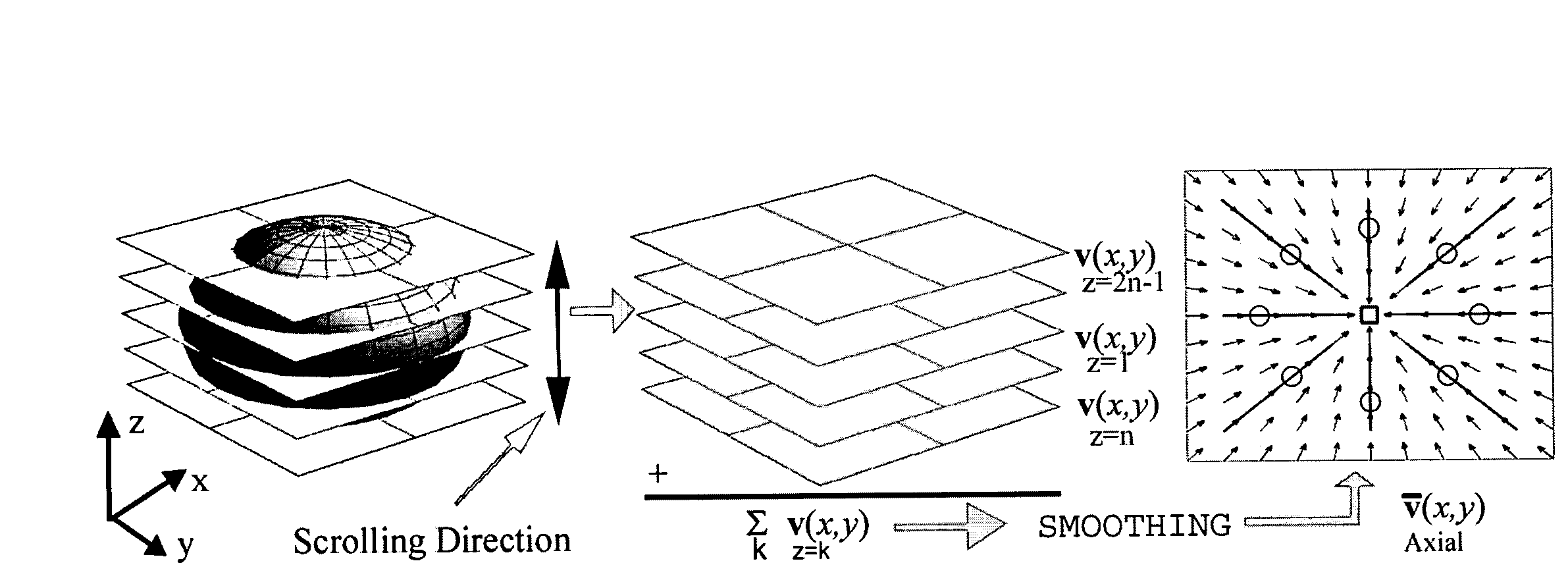
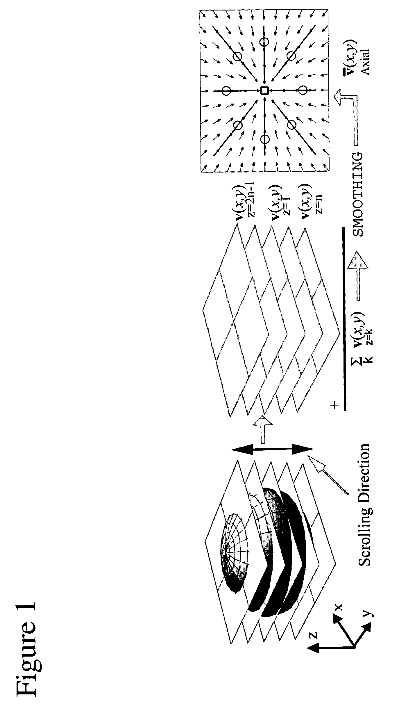
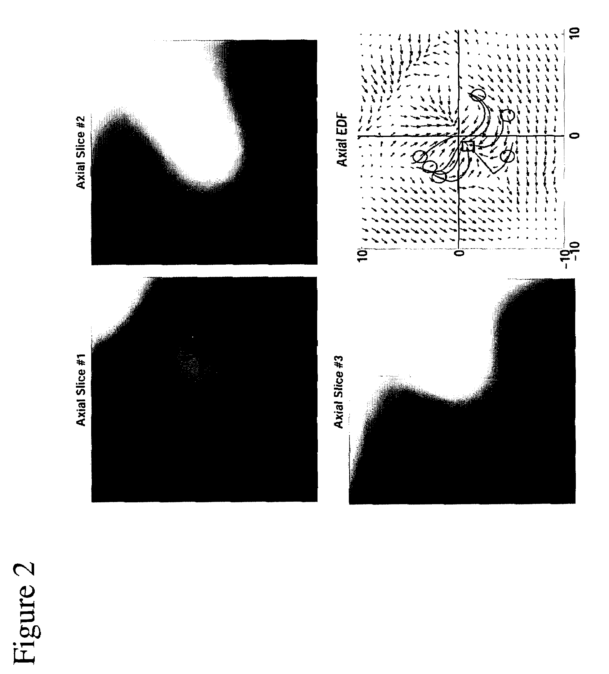
[0013]The method of the present invention could be referred to as an “Edge Displacement Field Method” (EDF), a “Gradient Field Method” (GF) or an “Optical Flow Field Method” (OFF) applied to detection and classification of structures of interests in medical images (See for an overview of optical flow computation S. S. Beauchemin et al., “The computation of optical flow,”Comput. Surv., vol. 27, no. 3, pp. 433-467, 1995). The present method is based on representing changes in 2-D cross-sections of three-dimensional (3-D) image data (e.g. ax...


PUM


Abstract

A method to detect and classify a structure of interest in a medical image is provided to enable high specificity without sacrificing the sensitivity of detection. The method is based on representing changes in three-dimensional image data with a vector field, characterizing the topology of this vector field and using the characterized topology of the vector field for classification of a structure of interest. The method could be used as a stand-alone method or as a post-processing method to enhance and classify outputs of a high-sensitivity low-specificity method to eliminate false positives.

Description

CROSS-REFERENCE TO RELATED APPLICATIONS[0001]This application is cross-referenced to and claims priority from U.S. Provisional Application 60 / 415,280 filed Sep. 30, 2002, which is hereby incorporated by reference.STATEMENT REGARDING FEDERALLY SPONSORED RESEARCH OR DEVELOPMENT[0002]The present invention was supported in part by grant number RO1 CA72023 from the National Institutes of Health (NIH / NCI). The U.S. Government has certain rights in the invention.FIELD OF THE INVENTION[0003]The present invention relates generally to medical imaging. More particularly, the present invention relates to methods for detecting and classifying a structure of interest in medical images to differentiate for instance (pre-)cancerous tissue from normal tissue.BACKGROUND[0004]Computed tomographic colonography (CTC) was first suggested in the early 1980s as a potential method for mass screening of colorectal cancer, the second leading cause of cancer deaths in the US. CTC was first realized in the 1990...

Claims


Application Information

Patent Timeline
Patent Type & Authority Patents(United States)
IPC IPC(8): G06K9/00G06T7/00
CPCG06K9/00201G06T7/0012G06T2207/30028G06T2207/30061G06V20/64
Inventor ACAR, BURAKBEAULIEU, CHRISTOPHER F.GOKTURK, SALIH B.TOMASI, CARLOPAIK, DAVID S.JEFFREY, JR., R. BROOKENAPEL, SANDY A.
Owner THE BOARD OF TRUSTEES OF THE LELAND STANFORD JUNIOR UNIV
Why Eureka
Try Eureka