
Router elevating mechanism

a technology of a router and a lowering mechanism, which is applied in the field of power tools, can solve the problems of time-consuming and difficult to conduct procedures,

Inactive Publication Date: 2007-10-02
BLACK & DECKER INC
View PDF161 Cites 23 Cited by
  • Summary
  • Abstract
  • Description
  • Claims
  • Application Information

AI Technical Summary

Benefits of technology

[0005]Accordingly, the present invention is directed to an elevating mechanism for power tools and in particu

Problems solved by technology

This procedure may be time consuming, require some skill / experience, may be difficult to conduct if the router is implemented with a router table, and the like.

Method used


Image

  • Router elevating mechanism
  • Router elevating mechanism
  • Router elevating mechanism

Examples


Embodiment Construction

[0016]Reference will now be made in detail to the presently preferred embodiments of the invention, examples of which are illustrated in the accompanying drawings. Those of skill in the art will appreciate that the principles of the present invention may be implemented on a variety of power tools, such as a cut-off tool, a laminate trimmer, a lock mortising machine, a jam saw, a plunge router, a standard router, and the like without departing from the scope and spirit of the present invention.

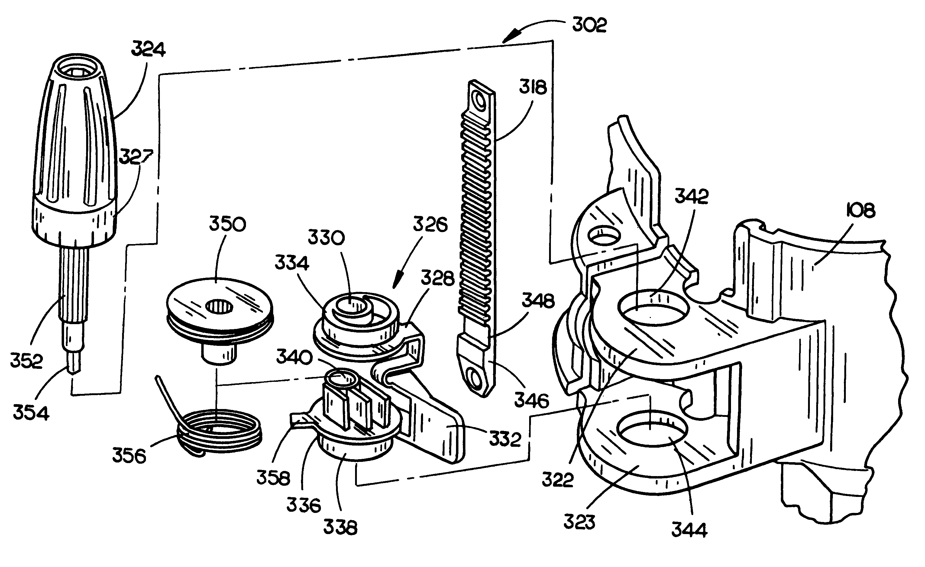
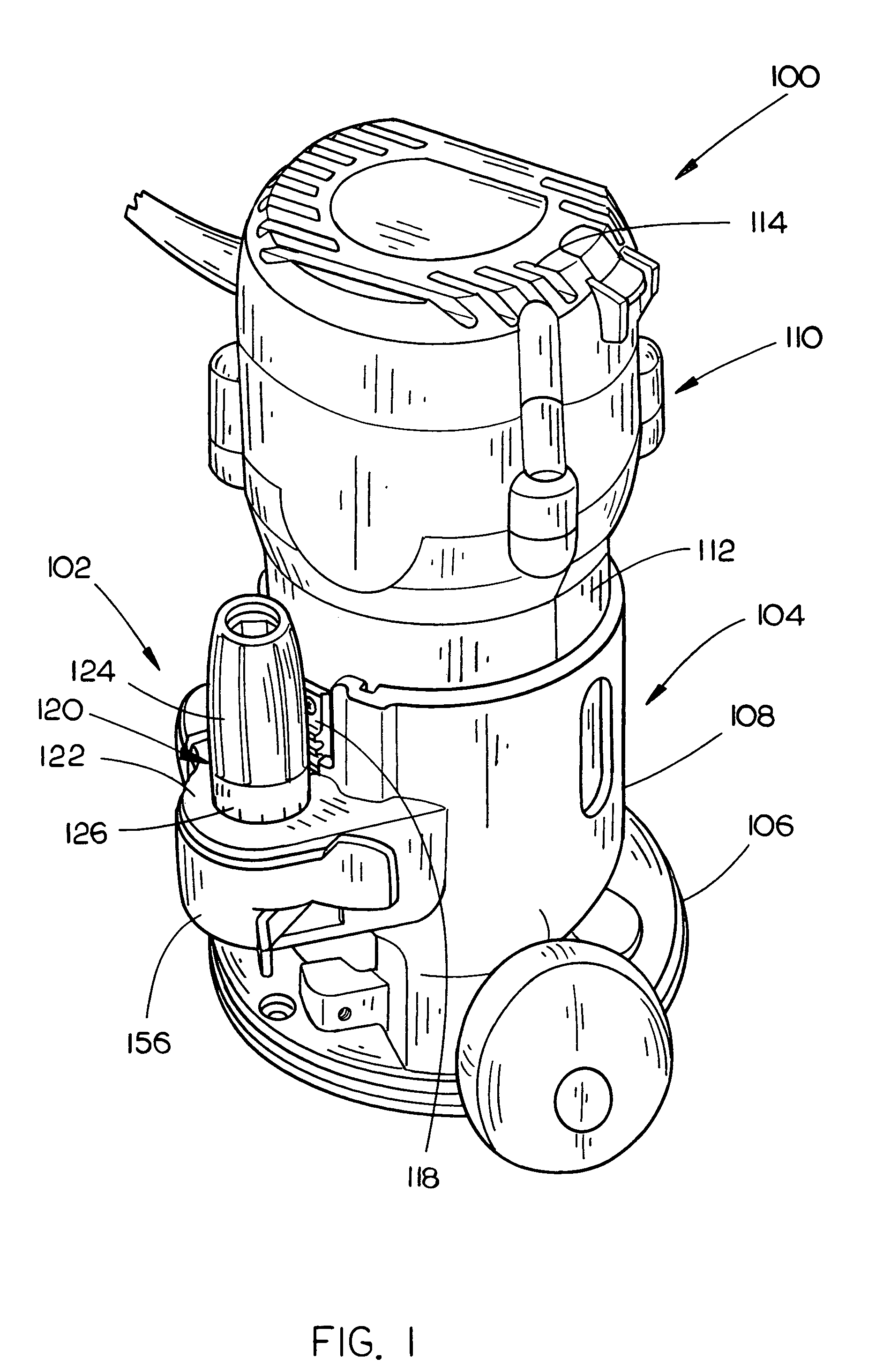
[0017]Referring to FIG. 1, a standard or fixed base router 100 including an elevating mechanism 102 in accordance with the present invention is discussed. The router 100 includes a base 104. In the current embodiment, the base 104 includes a substantially planer or support portion 106 for at least partially supporting the router 100 on a workpiece. Additionally, a sub base 110 such as a disk of plastic or the like material having a low coefficient of friction in comparison to the base material ...


PUM

PropertyMeasurementUnit
Mechanical propertiesaaaaaaaaaa

Abstract

The present invention is directed to an elevating mechanism, in particular to an elevating mechanism for routers, is configured for easy micro adjustment and coarse or macro adjustment. In an embodiment, a power tool includes a base configured to adjustably receive a motor housing for operating a working tool. A worm drive is pivotally coupled, in an eccentric configuration, to an eccentric lever. The eccentric lever is adjustably coupled to at least one of the housing or the base such that the eccentric lever is operable to cause the worm drive to be positioned into an engaged position with a rack assembly and a released position wherein the worm drive is remote from the rack assembly. The elevating mechanism is operable to permit rotational micro adjustment and macro manual adjustment wherein the worm drive is remote from the rack assembly for permitting coarse adjustment of the motor housing with respect to the base.

Description

CROSS REFERENCE[0001]The present application claims priority under 35 U.S.C. §119(e) to U.S. Provisional Patent Ser. No. 60 / 490,117, entitled: Router Elevating Mechanism, filed on Jul. 25, 2003, which is hereby incorporated by reference in its entirety.FIELD OF THE INVENTION[0002]The present invention relates to the field of power tools and particularly to an adjustment mechanism for varying the position of a working tool.BACKGROUND OF THE INVENTION[0003]Often power tools require both fine positional adjustment and coarse adjustment for various components and in particular to adjust the position of the working tool. For example, routers, shapers, cut-off tools and the like may require coarse or rough adjustment and require fine or precision adjustment. Typical adjustment systems tend to trade-off fine adjustment capability for the ability to make rapid coarse adjustments or allow for fine adjustment while requiring additional time and effort to make a coarse adjustment. For example,...

Claims


Application Information

Patent Timeline
IPC IPC(8): B23C1/20
CPCB27C5/10Y10T409/306552Y10T409/306608Y10T408/18
Inventor PHILLIPS, ALANSCHNELL, JOHN W.
Owner BLACK & DECKER INC
Features
  • Generate Ideas
  • Intellectual Property
  • Life Sciences
  • Materials
  • Tech Scout
  • Unparalleled Data Quality
  • Higher Quality Content
  • 60% Fewer Hallucinations
Learn More