Riding lawn mower lift

a technology for lawn mowers and lifts, which is applied in the direction of lifting devices, inclined ship lifting, construction, etc., can solve the problems of inefficiency of mowers, affecting the efficiency of mowers, and consuming the entire space between mowers

Inactive Publication Date: 2007-10-09
JONES RAYMOND A
View PDF15 Cites 13 Cited by
  • Summary
  • Abstract
  • Description
  • Claims
  • Application Information

AI Technical Summary

Problems solved by technology

The area between the mower deck and blades often becomes caked with grass clippings, especially if the grass is mowed when the grass is wet.
Eventually, the layers accumulate and consume the entire space between the mower deck and the blades.
Without this space, the mower becomes inefficient and eventually may quit cutting the grass entirely.
Additionally, this debris can damage the blades and strain the belts, engine and bearings.
This small clearance makes it difficult to clean the area under the mower deck.
The width of the mower deck provides additional challenges to reach all of the areas under the mower deck.
Because a typical lawn tractor weights 500 pounds to 1200 pounds or more, it is difficult to turn the lawn tractor on its side, especially for an individual, to access the area under the mower deck.
However, this often results in a situation in which the lawn tractor is inadequately supported, unstable and potentially dangerous or unsafe.

Method used


Image

  • Riding lawn mower lift
  • Riding lawn mower lift
  • Riding lawn mower lift

Examples


Embodiment Construction

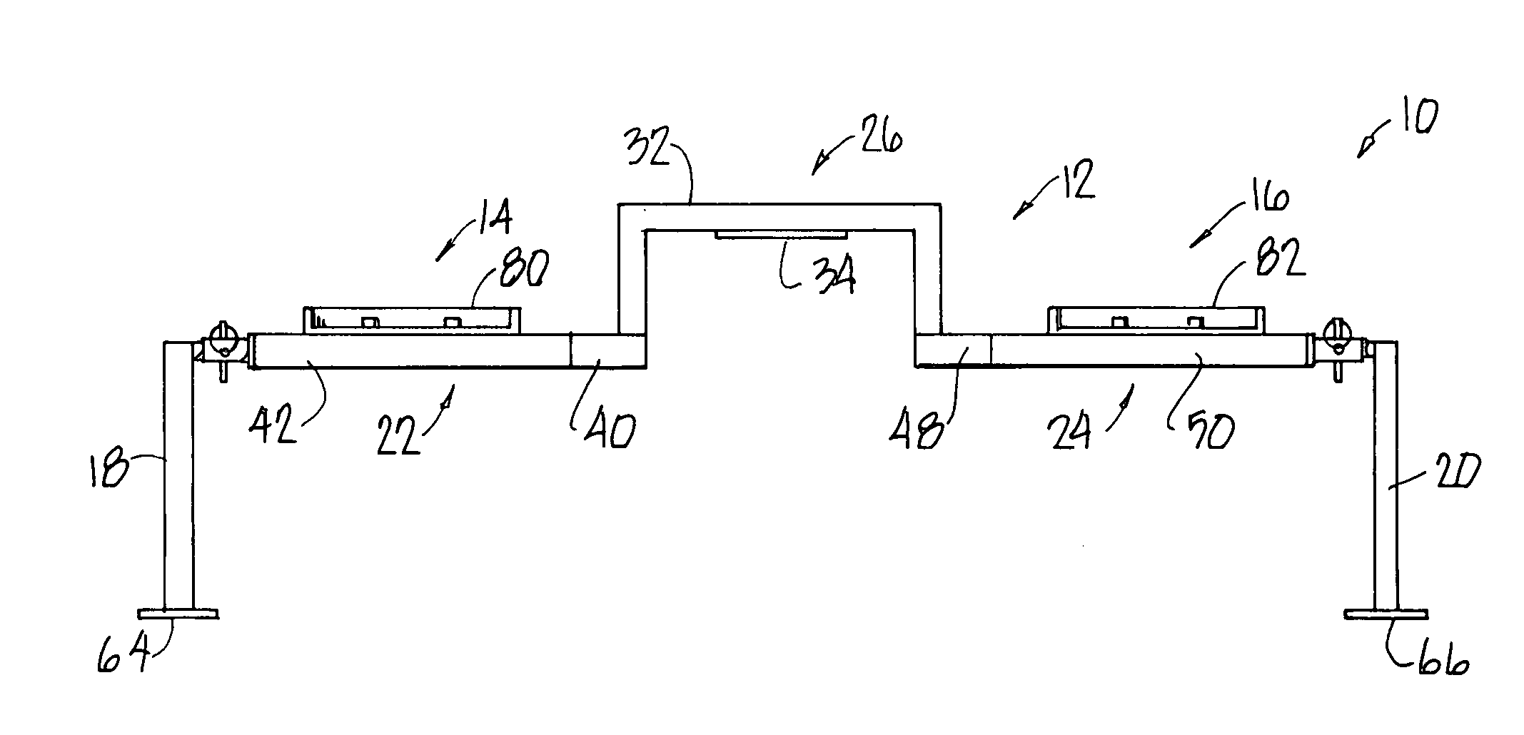
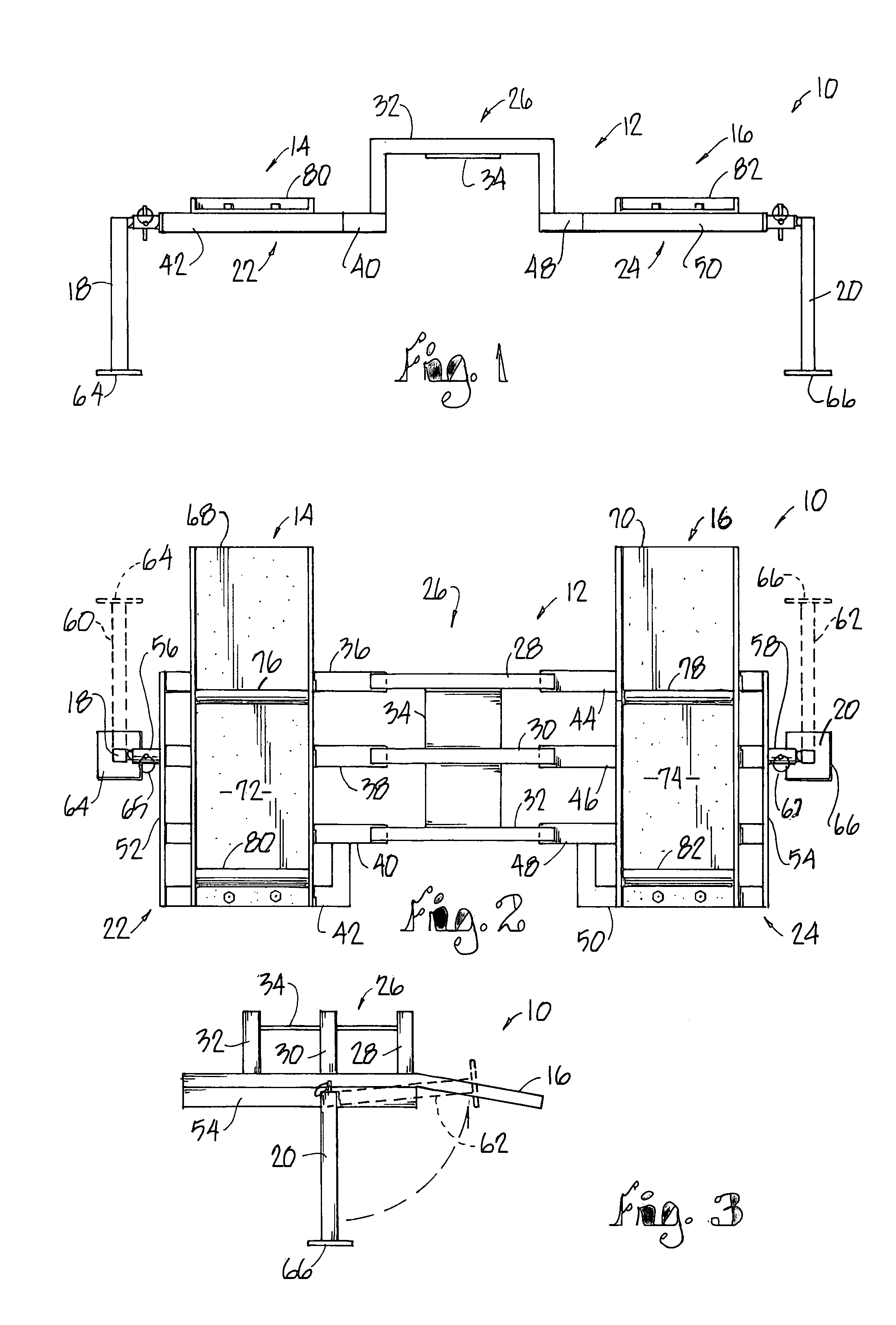
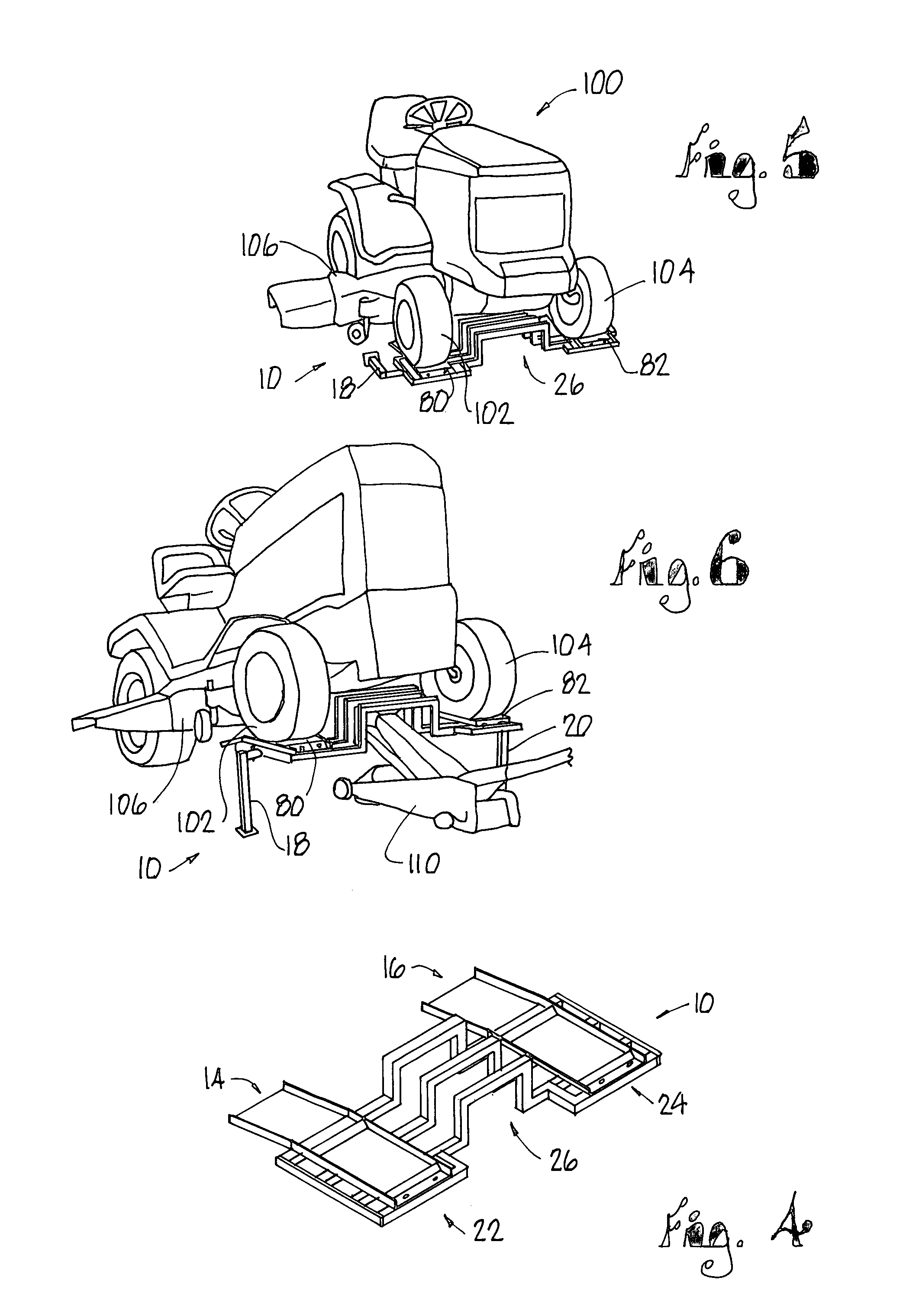
[0015]Referring to FIGS. 1-4 the lifting and support structure of the present invention is generally indicated by reference numeral 10. Lifting and support structure 10 includes a frame 12, ramps 14 and 16, and support legs 18 and 20. Frame 12 includes wheel support frames 22 and 24 and a center lift frame 26. Center lift frame includes three generally C-shaped cross members 28, 30 and 32 which are secured together by a lift pad 34. Opposite ends of the C-shaped cross members 28, 30 and 32 are secured to the cross members of the wheel support frames 22 and 24.

[0016]Support frames 22 and 24 include cross members 36, 36, 40 and 42, and 44, 46, 48 and 50, respectively. At one end, cross members 36, 38 and 40 are secured to one end of C-shaped cross members 28, 30, and 32, respectively, and at the other ends are secured together with an end plate 52. Cross member 42 is generally C-shaped and is secured to the cross member 40 at one end and to the end plate 52 at the opposite end.

[0017]S...


PUM


Abstract

A lift and support structure is provided for a lawn tractor which includes a frame with a center lift member secured to and separating a pair of wheel support members. Ramps are secured to the wheel support members to permit the front or rear wheels of the lawn tractor to be rolled onto or off of the lift and support structure. The center lift member is elevated above the wheel support members to permit a floor jack or other lifting mechanisms to be placed under the lift and support structure. A pair of support legs may be locked in a raised position to support the lawn tractor for safe and easy access to the underneath side of the tractor, and may be pivoted or folded to the side when the lift and support structure is in a lowered position.

Description

CROSS-REFERENCE TO RELATED APPLICATION[0001]This application claims the benefit of a prior filed, now abandoned application Ser. No. 60 / 564,787, filed Apr. 23, 2004, entitled RIDING LAWN MOWER LIFT.FIELD OF THE INVENTION[0002]The present invention relates to lifts and supports for lawn and garden tractors and, more particularly, to a structure for use in combination with a floor jack to lift the front wheels of a lawn or garden tractor and support the tractor in the raised position to allow safe access to the area under the mower deck.BACKGROUND OF THE INVENTION[0003]Lawn and garden tractors are commonly used to mow grass. The lawn tractor has a mower deck which houses one or more mower blades. The area between the mower deck and blades often becomes caked with grass clippings, especially if the grass is mowed when the grass is wet. The grass clippings often form layers which harden as the mower is used. Eventually, the layers accumulate and consume the entire space between the mowe...

Claims


Application Information

Patent Timeline
Patent Type & Authority Patents(United States)
IPC IPC(8): B66F7/00E02C3/00B66F7/24
CPCB66F7/243
Inventor JONES, RAYMOND A.
Owner JONES RAYMOND A
Why Eureka
Try Eureka