Racquet having cantilevered hoop portions

a cantilevered hoop and racquet technology, applied in the field of sports racquets, can solve the problems of undesirable increase in the polar moment of inertia of the racquet, the difficulty of swinging a large head racquet, and the difficulty of maneuvering a racquet with a higher polar moment of inertia

Inactive Publication Date: 2007-10-23
WILSON SPORTING GOODS
View PDF15 Cites 9 Cited by
  • Summary
  • Abstract
  • Description
  • Claims
  • Application Information

AI Technical Summary

Problems solved by technology

However, as the head size of a racquet increases, so does the polar moment of inertia of the racquet.
A racquet with a higher polar moment of inertia can be more difficult to maneuver, particularly at the net or upon return of serve, than a racquet with a lower moment of inertia.
Additionally, some users find a large head racquets to be more difficult to swing than racquets with normal sized heads.
Although such designs can provide a more targeted approach to increasing the performance of the racquet, such designs can also result in an undesirable increase in the polar moment of inertia of the racquet.
Further, such designs may also result in a head size that has an undesirable appearance, or an appearance that is markedly different from the look and design of traditional sport racquet designs.

Method used


Image

  • Racquet having cantilevered hoop portions
  • Racquet having cantilevered hoop portions
  • Racquet having cantilevered hoop portions

Examples


Embodiment Construction

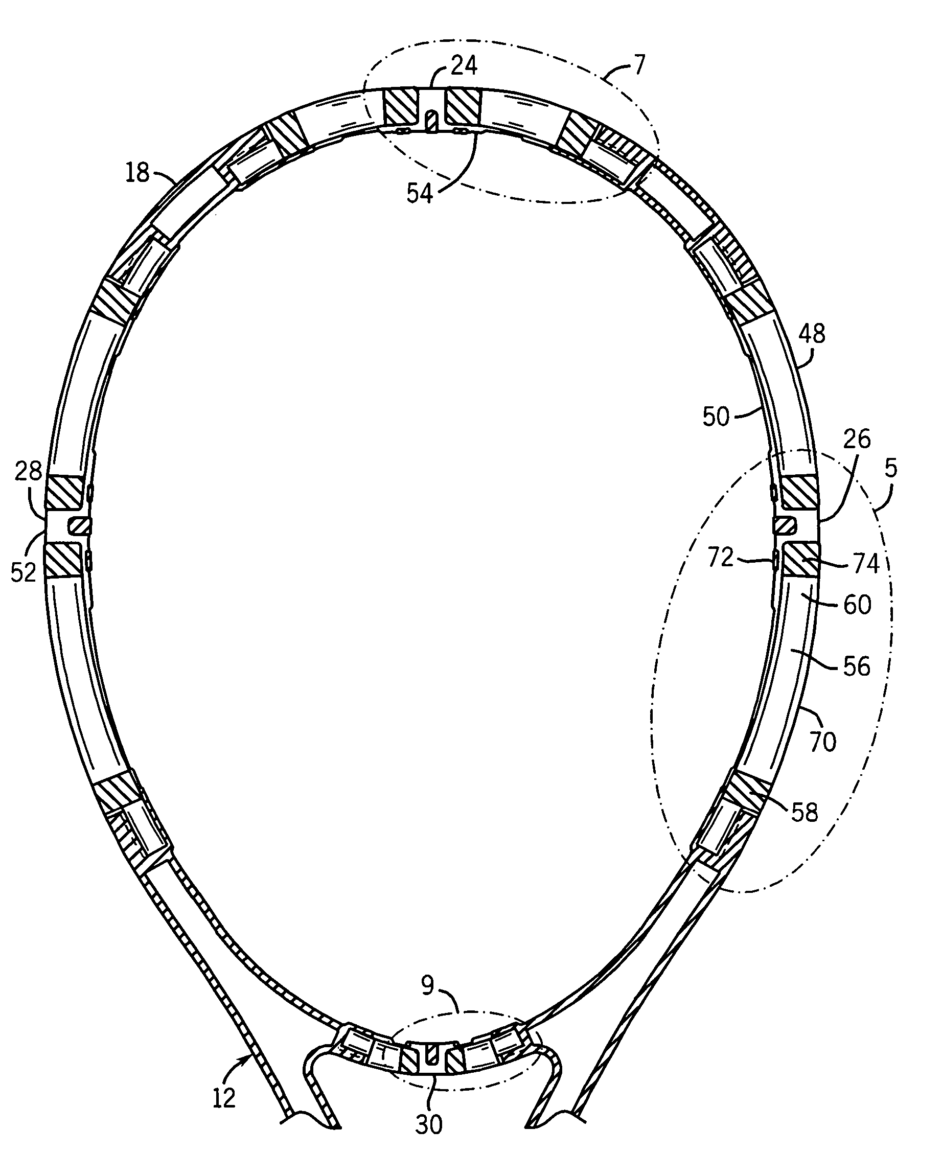
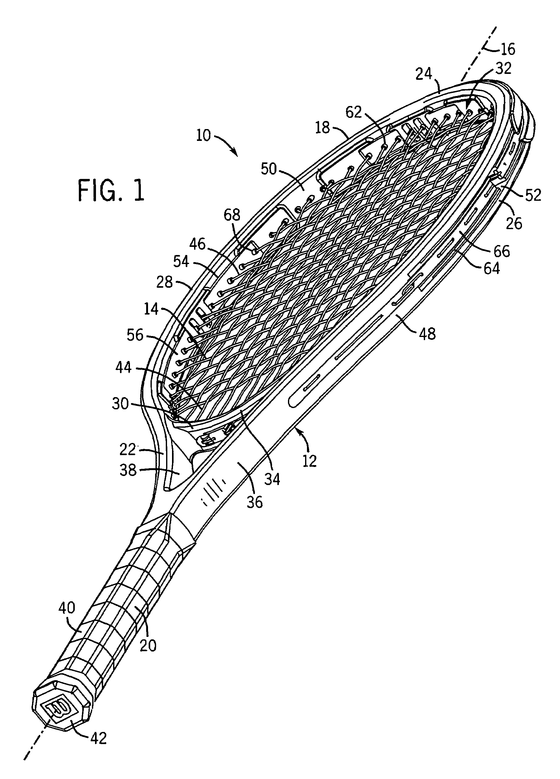
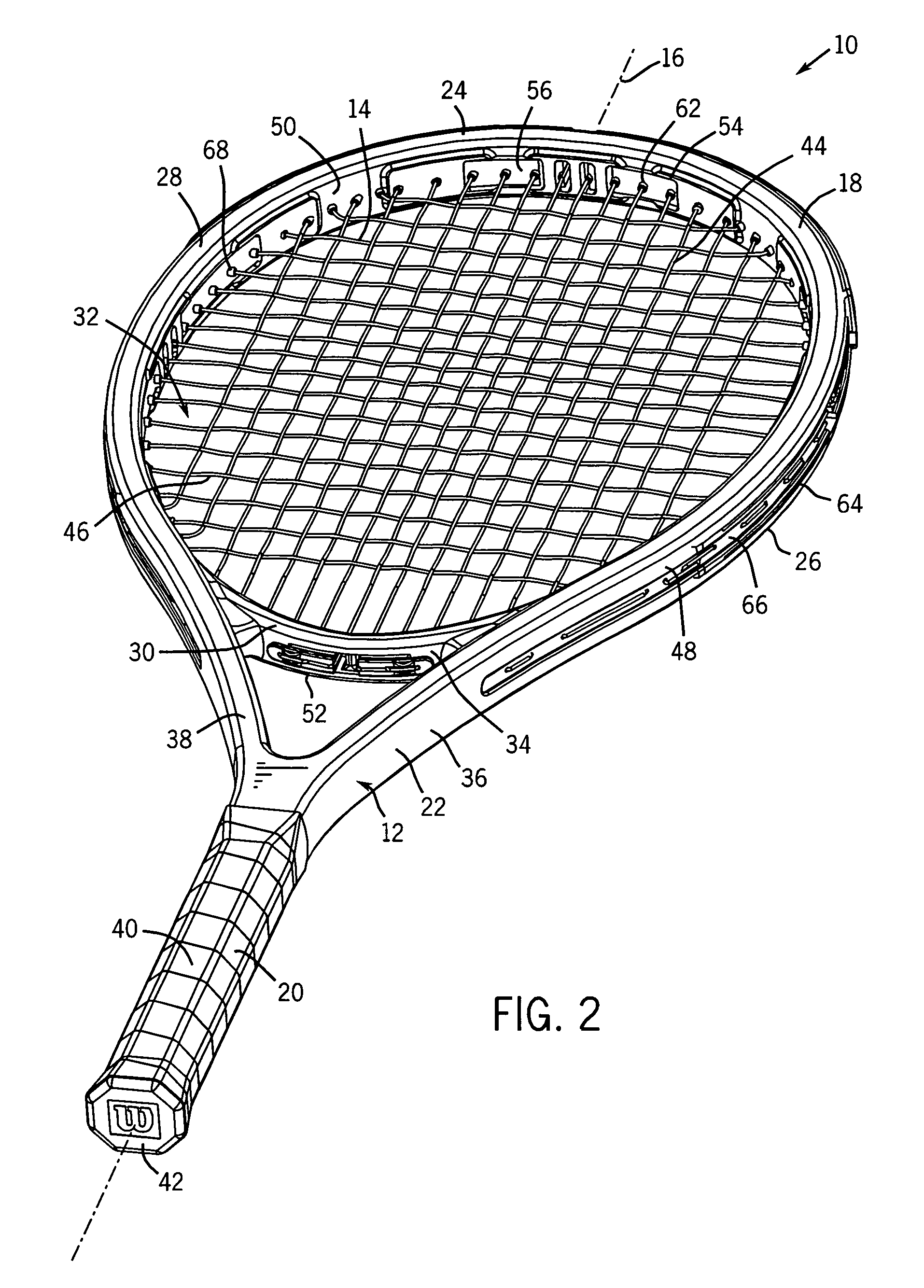
[0034]Referring to FIGS. 1 and 2, a sports racquet is indicated generally at 10. The racquet 10 of FIG. 1 is configured as a tennis racquet, however, the invention can also be formed as other types of sports racquets, such as, for example, a racquetball racquet, a squash racquet, or a badminton racquet. The racquet 10 includes a frame 12 and a string bed 14. The frame 12 is a tubular structure having a longitudinal axis 16 and including a head portion 18, a handle portion 20, and a throat portion 22 coupling the head and handle portions 18 and 20. The frame 12 is formed of a lightweight, durable material, preferably a carbon-fiber composite material. Alternatively, the frame 12 can be formed of other materials including metallic alloys, other composite materials, wood, or combinations thereof. The head portion 18 forms a distal region 24, first and second side regions 26 and 28, and a proximal region 30, which collectively define a string bed area 32 for receiving and supporting the...


PUM


Abstract

A sports racquet including a frame, a string bed, and at least one cantilevered member. The frame includes a head portion coupled to a handle portion. The head portion includes a distal region, first and second side regions, and a proximal region. A string bed is formed of a plurality of cross string segments and a plurality of main string segments. The cantilevered member has a first section coupled to one of the regions, such that at least one point on the first section remains substantially fixed in relation to the region to which the first section is coupled, and a second section that is deflectable relative to the region to which the first section is coupled. At least one of the string segments is operably engaged with the member, such that when a ball impacts the string segment, the second section deflects inward toward the string bed.

Description

FIELD OF THE INVENTION[0001]The present invention relates generally to a sports racquet. In particular, the present invention relates to racquet including a head portion having at least one cantilevered member.BACKGROUND OF THE INVENTION[0002]Sport racquets, such as tennis, racquetball, squash and badminton racquets, are well known and typically include a frame having a head portion coupled to a handle portion. The head portion supports a string bed having a plurality of main string segments interwoven with a plurality of cross string segments. Many racquets also include a throat portion positioned between and connecting the handle portion to the head portion. The typical string bed of a sports racquet includes a central region, that provides the most responsiveness, the greatest power and the best “feel” to the player, upon impact with a ball, and a peripheral region. The central region, commonly referred to as the “sweet spot,” is typically defined as the area of the string bed th...

Claims


Application Information

Patent Timeline
Patent Type & Authority Patents(United States)
IPC IPC(8): A63B49/02
CPCA63B49/02A63B59/0092A63B49/06A63B2209/14A63B2209/00A63B2209/023A63B2049/0217A63B60/52A63B60/54A63B49/022A63B49/028A63B49/025
Inventor MCMILLAN, WILLIE H.SEVERA, WILLIAM D.LOEFFLER, DONALD G.
Owner WILSON SPORTING GOODS
Why Eureka
Try Eureka