Method and apparatus for reproducing recording mark below diffraction limit of light from optical recording medium

a technology of optical recording medium and recording mark, which is applied in the field of reproducing information, can solve problems such as deterioration of level jitter, level error, and limitations in the numerical aperture of the objective lens, and achieve the effect of reducing level jitter and good error characteristics

Inactive Publication Date: 2007-10-30
CANON KK
View PDF20 Cites 5 Cited by
  • Summary
  • Abstract
  • Description
  • Claims
  • Application Information

AI Technical Summary

Benefits of technology

[0031]The present invention has been made in view of the conventional problems described above, and is aimed at providing a method and apparatus for reproducing information from an optical recording medium, with w...

Problems solved by technology

However, the improvement of the laser wavelength and the numerical aperture of the objective lens has limitations.
Those high-frequency noise and waveform distortion lead to a level error at the time of PR detection, that is, those become a cause for deterioration of level jitter in the signal level histogram shown in FIG. 9G.
However, the LPF affects not only the noises but also the inclinations of the rising edge and falling edge of signal polarity changing of the rectangular reproduction signal.
Conseque...

Method used


Image

  • Method and apparatus for reproducing recording mark below diffraction limit of light from optical recording medium
  • Method and apparatus for reproducing recording mark below diffraction limit of light from optical recording medium
  • Method and apparatus for reproducing recording mark below diffraction limit of light from optical recording medium

Examples


first embodiment

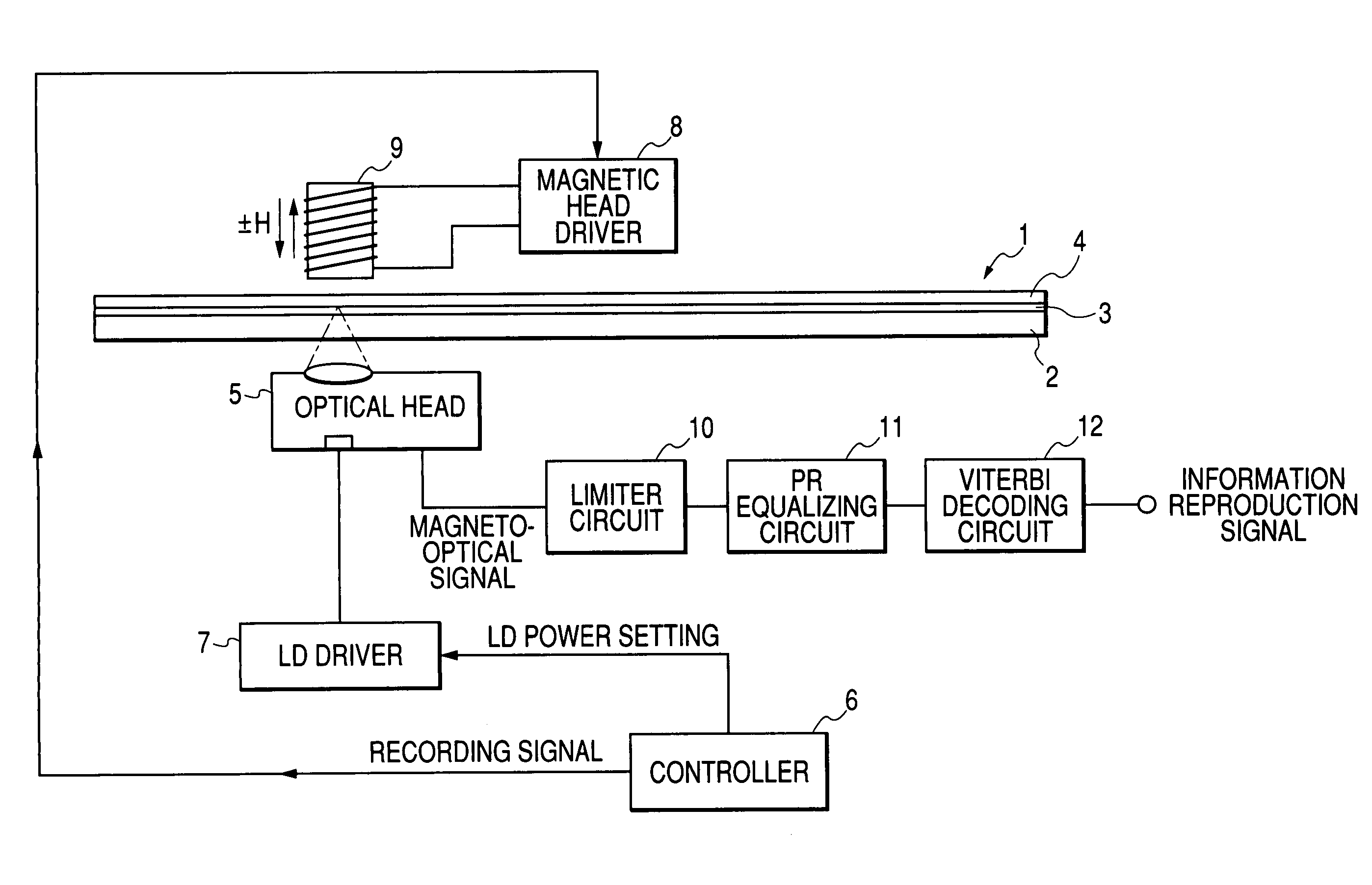
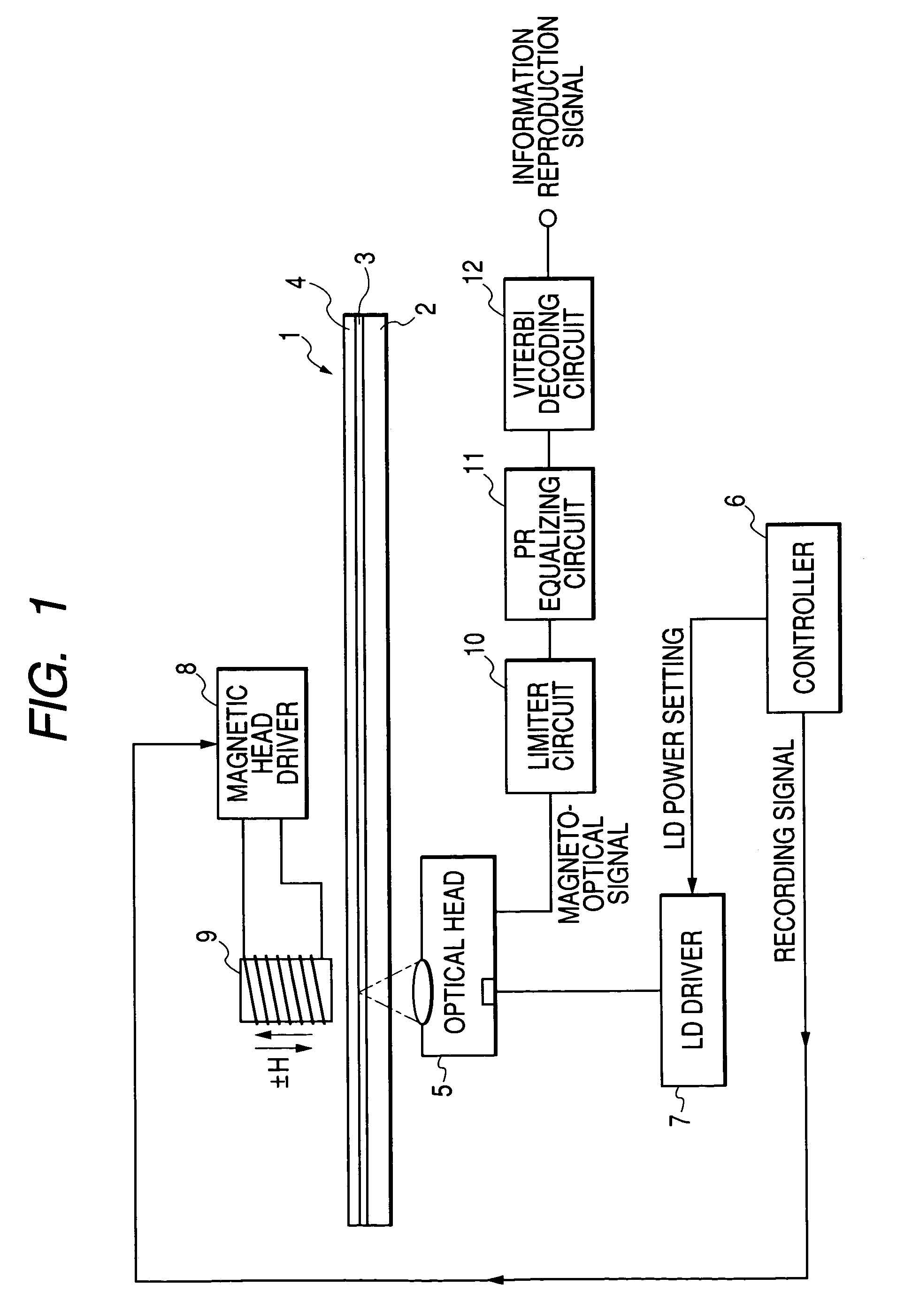
[0046]FIG. 1 is a block diagram showing a construction of a first embodiment of the magneto-optical recording / reproduction apparatus according to the present invention. In FIG. 1, each portion that is the same as that of the conventional apparatus shown in FIG. 6 is given the same reference numeral and the description thereof will be omitted. That is, a magneto-optical disk 1 of domain wall displacement detection type, a substrate 2, a magneto-optical recording film 3, and an optical head 5 are each the same as that shown in FIG. 6.

[0047]The optical head 5 includes a semiconductor laser for recording / reproduction, a condensing lens for condensing a laser light flux of the semiconductor laser, an actuator for driving the condensing lens, a beam splitter, and a polarizing beam splitter, a photosensor for detecting reflection light from the magneto-optical disk 1, and the like. The wavelength of the semiconductor laser in the optical head λ is set to, for example, 650 nm and the NA of ...

second embodiment

[0063]FIG. 4 is a block diagram showing a second embodiment of the present invention. FIG. 4 differs from FIG. 1 in that a reproduction signal processing circuit 13 is provided in place of the limiter circuit 10 and the PR equalizing circuit 11, and other constructions are the same as those shown in FIG. 1. The reproduction signal processing circuit 13 is a digital signal processing circuit that performs the reproduction signal sampling, limiter limitation, and PR equalization as digital processing. The fundamental recording operation and the fundamental reproduction operation principle according to this embodiment are the same as those in the first embodiment.

[0064]Next, a reproduction signal processing method according to this embodiment will be described with reference to FIGS. 5A to 5H. A case where a (1, 7) RLL code is used as a modulation code will be described as an example. FIG. 5A shows a recording information string, FIG. 5B shows a recording signal string, FIG. 5C shows a...


PUM


Abstract

The object of the present invention is to realize reduction of the level jitter generated from a noise component at a signal saturation level or a waveform distortion in a portion except for signal polarity portions (rising edge and falling edge), and good error characteristics. In the present invention, a predetermined upper or lower limit value is set to reproduction signals, the reproduction signals are subjected to a limiter processing for correcting reproduction signals of the upper limit value or more, or the lower limit value or less to the level of the upper limit value or the lower limit value, respectively, the signal subjected to the limiter processing is subjected to a partial response equalizing (PR equalizing) processing, and PR reproduction is performed to improve the level jitter at PR detection time and the error rate at information reproduction time.

Description

BACKGROUND OF THE INVENTION[0001]1. Field of the Invention[0002]The present invention relates to a method and apparatus for reproducing information by irradiating an optical recording medium with a reproduction light beam, and in particular to a method and apparatus for reproducing information using a magneto-optical recording medium of domain wall displacement detection type.[0003]2. Related Background Art[0004]Conventionally, a magneto-optical recording medium has been used for a rewritable high-density recording system in which information is recorded by writing magnetic domains in a magnetic thin film using the thermal energy of a semiconductor laser and from which the information is read using a magneto-optical effect. Also, in recent years, a demand has grown to further enhance the recording density of this magneto-optical recording medium to obtain a large-capacity recording medium.[0005]By the way, the linear recording density of an optical disk, such as a magneto-optical re...

Claims


Application Information

Patent Timeline
IPC IPC(8): G11B11/03G11B20/10G11B5/09G11B11/00G11B11/105
CPCG11B20/10009G11B20/10296G11B20/10046G11B11/10515G11B2220/2525
Inventor MIYAOKA, YASUYUKI
Owner CANON KK
Why Eureka
Try Eureka