Measurement system and method

a measurement system and measurement system technology, applied in the direction of measuring tapes, instruments, using mechanical means, etc., can solve the problems of unsuitable window treatment, inability to measure, increase costs, etc., and achieve the effect of eliminating lost time and revenu

Inactive Publication Date: 2007-11-13
FAULK FR +1
View PDF12 Cites 47 Cited by
  • Summary
  • Abstract
  • Description
  • Claims
  • Application Information

AI Technical Summary

Benefits of technology

[0016]By incorporating the reference strips into the photograph along with the biographic information measurements can be verified to ensure the manufacture and installation of an acceptable treatment solution and thereby eliminate the lost time and revenue resulting from inaccurate measurements. The present invention also allows relatively unskilled personnel to take measurements and provide the measurements to a third party for verification. While the present invention has been discussed in connection with window treatments, the present invention is not limited to window treatments but may be used for generating, verifying, and providing measurements for a variety of objects.

Problems solved by technology

The biggest stumbling block in the industry has proven to be the first step—the ability to efficiently obtain accurate and complete measurements of the windows.
But inaccurate measurements remain a bane of the industry, often leading to window treatments that are unsuitable for installation and requiring the remeasuring of the windows and the remanufacture and reinstallation of the treatments.
This results in increased costs, unacceptable delays, and unsatisfied customers.
This process is susceptible to errors and mistakes however, and even in cases where the sketch itself is accurate, critical information beneficial to designers and manufacturers is often omitted.
For example, the person taking the measurements often fails to mention that there is a door, recess, or adjacent wall near the window that could affect the design, manufacture and installation of the treatment.
Furthermore, a party receiving such a sketch has no way to readily verify its accuracy and therefore risks designing or manufacturing a treatment of the wrong dimensions.
This is especially true when the actual manufacture of the treatment is done overseas, making it unrealistic for the manufacturer to take the measurements.
Language barriers may further complicate matters.
Thus, the manufacturer is often unable to obtain accurate and verifiable measurements prior to manufacture the risk of providing unacceptable product.
This inability to provide accurate and verifiable measurements ripples through the entire window treatment process.
For example, parties that design window treatment solutions can ill afford to take time from their more profitable design tasks to travel to the installation site and take the measurements themselves.
Because these measurements are not readily verifiable however, inaccuracies in the measurements often go undetected resulting in unacceptable treatments which must be redone, often at significant cost.
While it is possible to photograph windows and provide the resulting photographs to another party, it is difficult to verify measurements associated with such photographs.
For example, it is impractical to generate such photographs on a 1:1 scale with the actual window so a user can measure the photographic image of the window to determine the measurements of the actual window.
But photographs can be taken from a variety of angles and distances making it difficult to derive a standard conversion scale.
Perspective is one effect that prevents the easy and accurate determination of the size of an object from a photograph.
Further complicating the matter are distortions which often affect images.
Distortions may also result from the particular viewing mechanism used to view the photograph, such as a computer monitor.
Thus, a typical photograph of a window does not provide a viewer of the photograph with a complete and verifiable biography of the window from which to generate window treatments.
While the above discussion relates to windows and window treatments, similar problems and issues arise when measuring other objects.

Method used


Image

  • Measurement system and method
  • Measurement system and method
  • Measurement system and method

Examples


Embodiment Construction

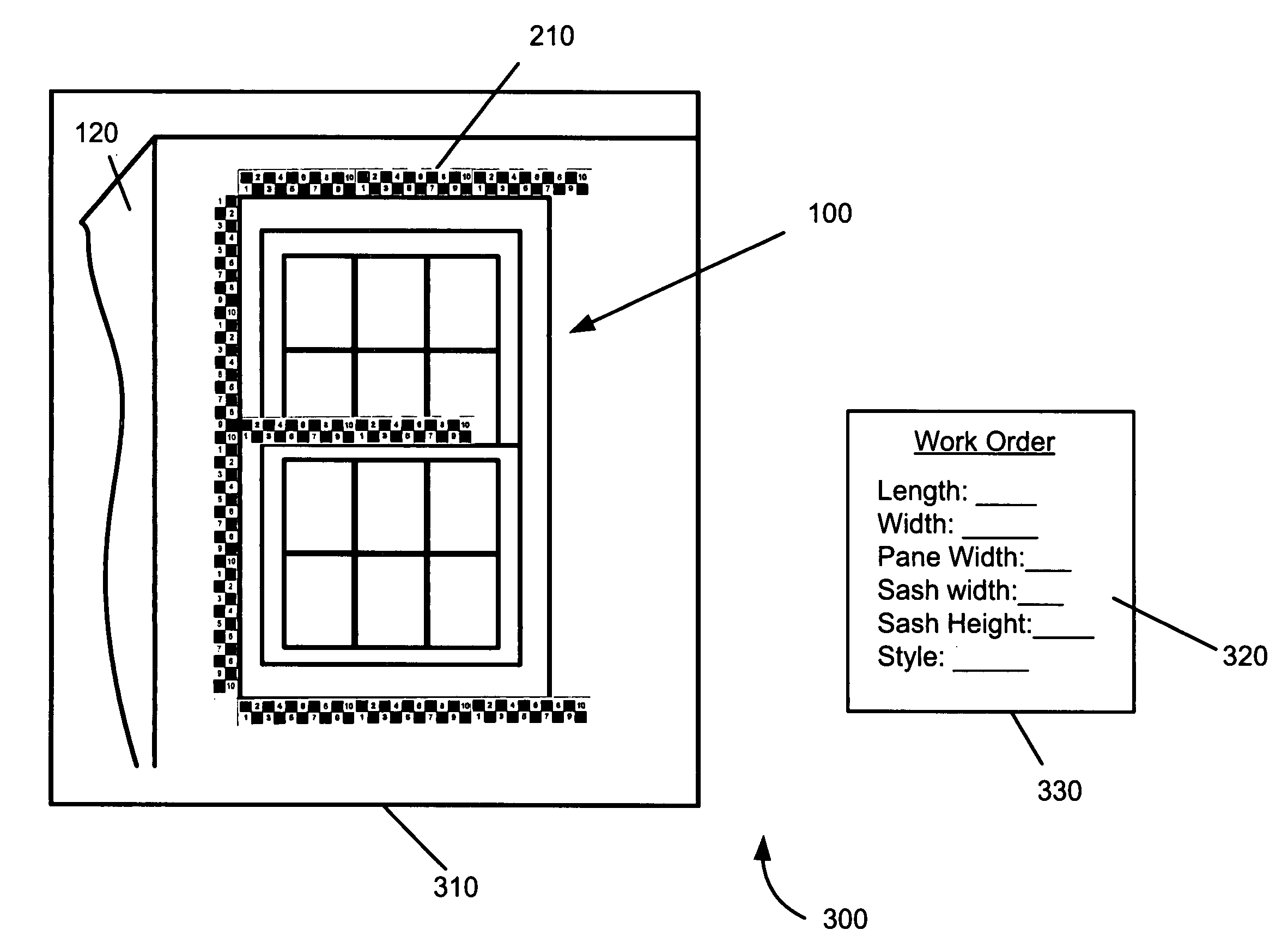
[0032]As required, exemplary embodiments of the present invention are disclosed herein. These embodiments should be viewed with the knowledge that they are only examples and that the invention may be embodied in many various and alternative forms. The figures are not to scale and some features may be exaggerated or minimized to show details of particular elements, while related elements may have been eliminated to prevent obscuring novel aspects. Well known structures and functions have not been shown or described in detail to avoid unnecessarily obscuring the description of the embodiments of the invention. Therefore, specific structural and functional details disclosed herein are not to be interpreted as limiting, but merely as a basis for the claims and as a representative basis for teaching one skilled in the art to variously employ the present invention.

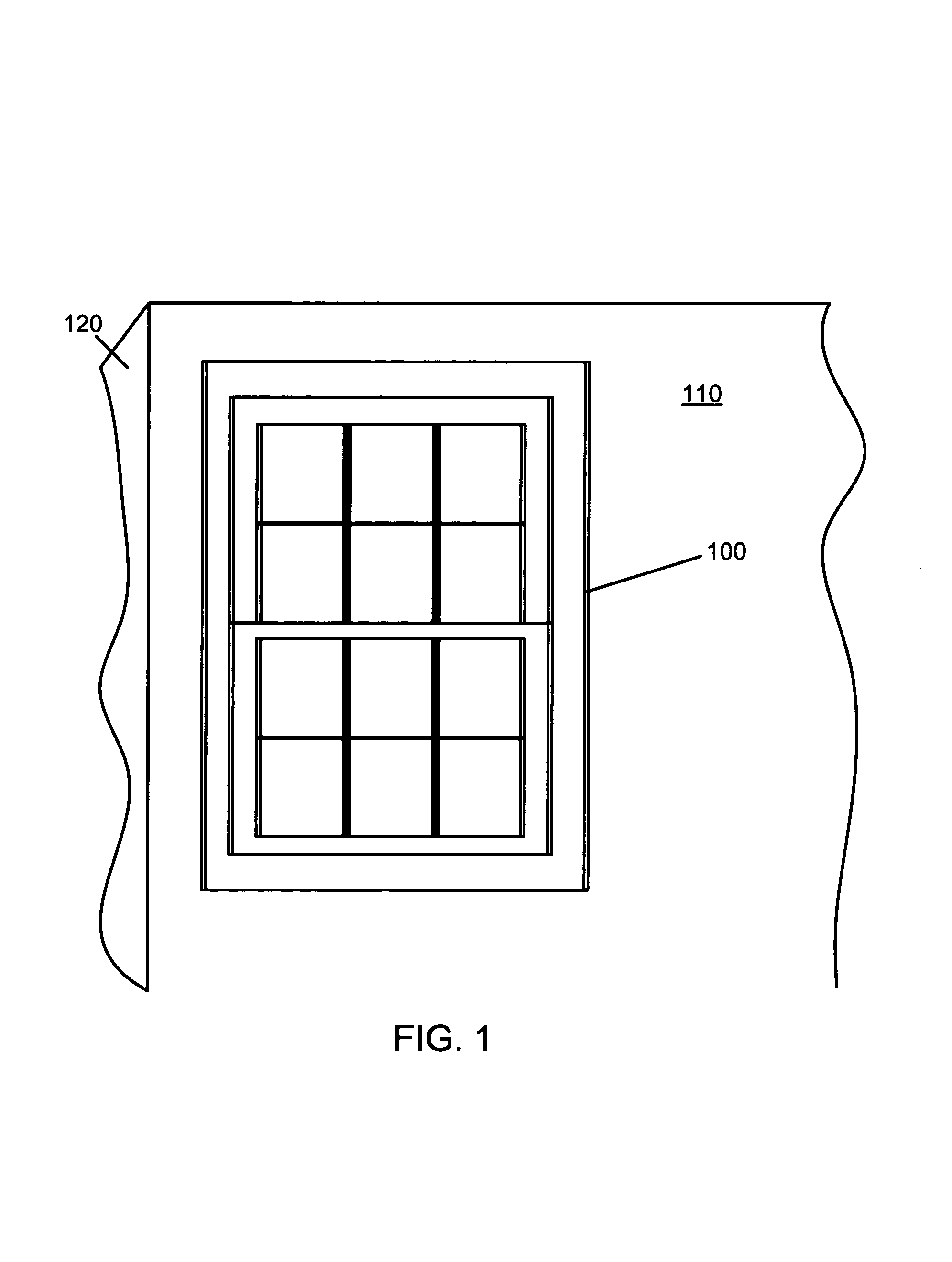
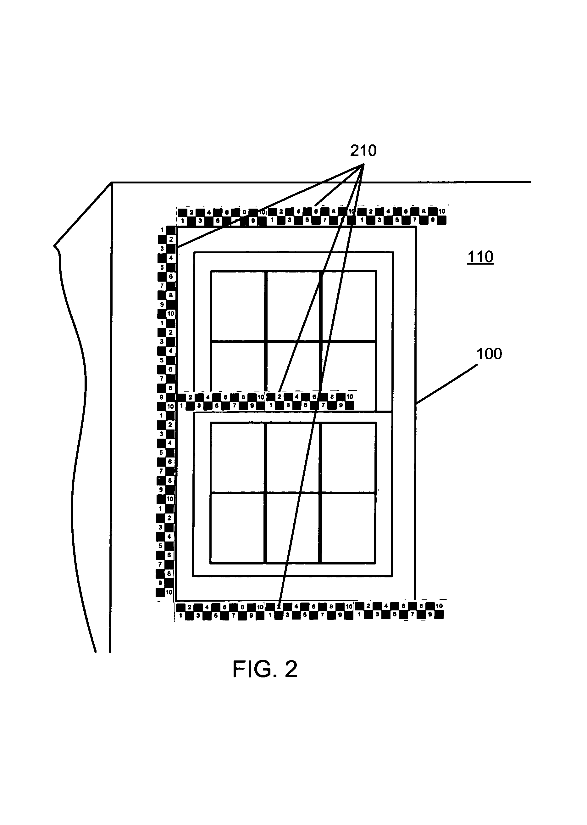
[0033]Turning to the figures wherein like numerals represent like elements throughout, FIG. 1 illustrates a window 100 for whi...


PUM


Abstract

An apparatus and method are provided for accurately recording measurements of a window and producing accurate window treatments. A reference strip is provided having measurement indicia thereon, such as a checkerboard pattern of squares of predetermined sizes. The reference strip may be placed proximate a window and photographed. The size of the window may be accurately determined from the resulting photograph using the associated reference strip. The window may also be measured and the measurements stored as biographic data and associated with the photograph to form an accurate and verifiable window biography. The biography may be provided to another party, such as a treatment manufacturer, who verifies the measurements of the biographic data using photograph and produces a suitable window treatment according to the measurements.

Description

FIELD OF THE INVENTION[0001]The present invention relates to methods and systems of measurement. More particularly, the present invention relates to devices, systems, and methods for obtaining, recording, verifying, and providing accurate measurements.BACKGROUND[0002]It is often desirable to measure an object and provide the resulting measurements to another party. For example, one may measure a window, floor, wall, or room and provide the measurements to another party for the design, manufacture, and installation of products such as window treatments, carpeting, wall paper, etc.[0003]The importance of obtaining accurate measurements and providing the accurate measurements to another party is illustrated by the window treatment industry. The building industry has created windows of varying sizes and shapes which have been incorporated into home designs in ways limited only by the imagination of architects and builders. An effective window treatment solution must be both decorative a...

Claims


Application Information

Patent Timeline
Patent Type & Authority Patents(United States)
IPC IPC(8): G01B3/10E06B3/00
CPCG01C11/00
Inventor FAULK, FRANKCOPE, RICHARD C.
Owner FAULK FR
Why Eureka
Try Eureka