
Cable connector

a technology of cable connectors and connectors, applied in the direction of electrical equipment, connection, coupling device connection, etc., to achieve the effect of sufficient opening of the inserting por

Active Publication Date: 2007-11-20
YAMAICHI ELECTRONICS
View PDF49 Cites 19 Cited by
  • Summary
  • Abstract
  • Description
  • Claims
  • Application Information

AI Technical Summary

Benefits of technology

[0013]While taking the above-mentioned problems into account, an object of the present invention is to provide a cable connector for electrically connecting one end of a cable to a circuit board so that a terminal section of a flexible printed circuit board does not come off of the cable connector even if a pulling force or a bending moment larger than a predetermined value is applied to the terminal section on one side of the flexible printed circuit board, while ensuring sufficient opening of an inserting port.

Problems solved by technology

The repeated reciprocation of the electric equipment, for example, may cause such a load.

Method used


Image

  • Cable connector
  • Cable connector
  • Cable connector

Examples


Embodiment Construction

[0036]FIGS. 3 and 4 illustrate an appearance of one embodiment of the inventive cable connector.

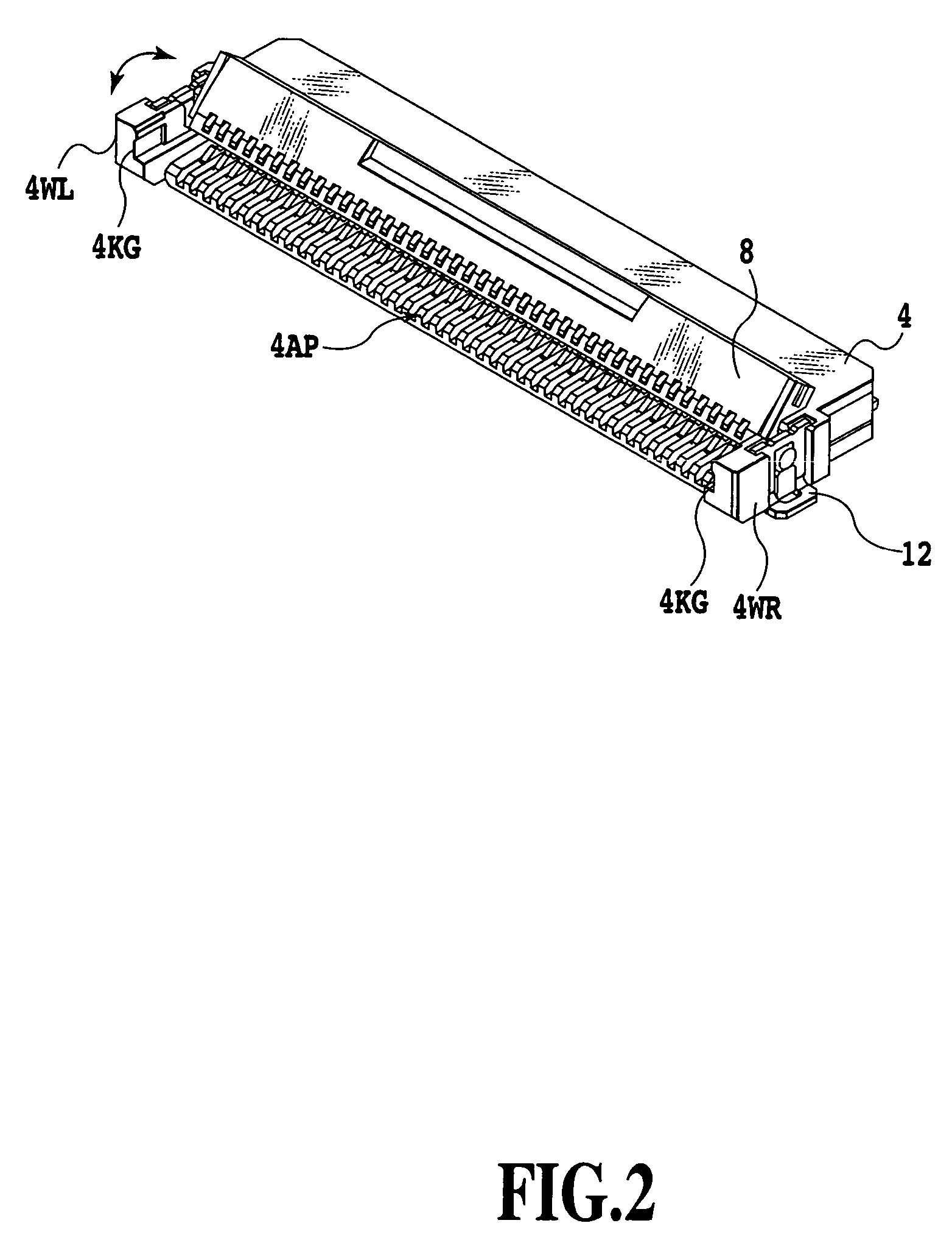
[0037]In FIG. 3, the cable connector includes a connector body 4 having a cable accommodating section 4A, arranged on a printed circuit board 2, a plurality of contact terminals 10ai (i=2 to n, n is an positive integer) (see FIG. 6) provided in the cable accommodating section 4A (see FIG. 5) in the connector body 4, for electrically connecting an electrode parts of the terminal section in the flexible printed circuit board 2, and an actuator member 8 supported in a rotatable manner to opposite lateral walls 4WR and 4WL of the connector body 4, for fixing or releasing the terminal section in the flexible printed circuit board 6 to the contact terminals 10ai.

[0038]The flexible printed circuit board 6 is referred, for example, to YFLEX (registered trade mark) and has a structure wherein a plurality of conductive layers, each covered with a protective layer are formed on an insulative substr...


PUM


Abstract

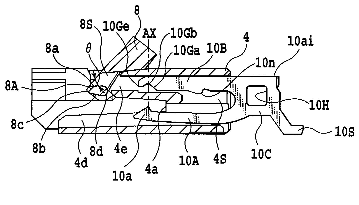
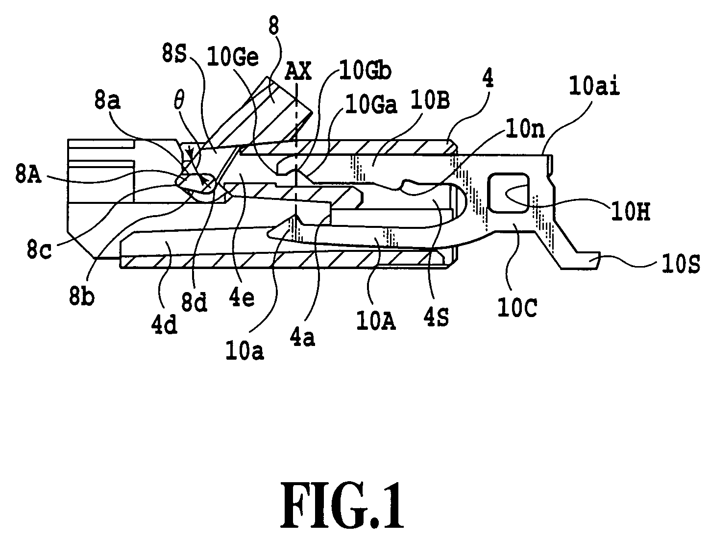
In a cable connector, a sliding surface in a pressing portion of an actuator member is rotatable or movable relative to an arc-shaped portion and slant part of a contact terminal.

Description

[0001]This application claims priority from Japanese Patent Application Nos. 2005-199018 filed Jul. 7, 2005 and 2006-163733 filed Jun. 13, 2006, which are incorporated hereinto by reference.BACKGROUND OF THE INVENTION[0002]1. Field of the Invention[0003]The present invention relates to a cable connector for electrically connecting one ends of cables to a wiring board.[0004]2. Description of the Related Art[0005]A cable connector is used in practice for electrically connecting electric parts with each other in the interior of an electronic apparatus. For example, the electric parts are electrically connected to a printed circuit board via a flexible printed circuit board (FPC) or a flexible flat cable (FFC). There are a rotary type and a slide type in the cable connector used in practice, which are different in a method for fixing a cable. As disclosed in Japanese Patent Application Laid-open No. 2001-357920, Japanese Patent Nos. 3579827 and 2692055 and Japanese Patent Application La...

Claims


Application Information

Patent Timeline
Patent Type & Authority Patents(United States)
IPC IPC(8): H01R12/24
CPCH01R12/88H01R12/79H01R12/82
Inventor TAKAHIRA, HIROSHI
Owner YAMAICHI ELECTRONICS
Learn More