Battery cover assembly for portable electronic device

a technology for electronic devices and battery covers, which is applied in the direction of cell components, coupling device connections, instruments, etc., can solve the problems of affecting the service life of batteries, the awkward detachment of battery covers by users, and the tendency of battery covers to be damaged

Inactive Publication Date: 2007-12-04
FIH (HONG KONG) LTD +1
View PDF10 Cites 123 Cited by
  • Summary
  • Abstract
  • Description
  • Claims
  • Application Information

AI Technical Summary

Benefits of technology

[0005]In one preferred embodiment, a battery cover assembly includes a battery cover, a housing, and a locking member. The battery cover has a receiving hole defined therein. The receiving hole is located proximate to one end of the battery cover. The housing has a locking part defined in one end thereof. The locking part includes a receiving groove and a resisting portion protruding from a bottom of the groove. The locking member has an operating portion and a latching ear. The operating portion is rotatably mounted in the receiving hole of the battery cover. The latching ear extends from one side of the operating portion. The latching ear is movably the locking part of the housing. When the latching ear moves to abut a first side of the resisting portion in the receiving groove, the operating portion is rotated to a predetermined angle such that the latching ear abuts an opposite second side of resisting portion.

Problems solved by technology

The battery has to be replaced by opening the battery cover when, for example, the battery is damaged or dead (e.g., no longer rechargeable).
However, when detaching the battery cover, relatively great force needs to be exerted thereon.
Therefore it can be awkward for a user to detach the battery cover, and the battery cover is susceptible to damage during such operation.

Method used


Image

  • Battery cover assembly for portable electronic device
  • Battery cover assembly for portable electronic device
  • Battery cover assembly for portable electronic device

Examples


Embodiment Construction

[0014]A battery cover assembly of the present invention is suitable for applications including portable electronic devices, such as mobile phones, PDAs, and so on.

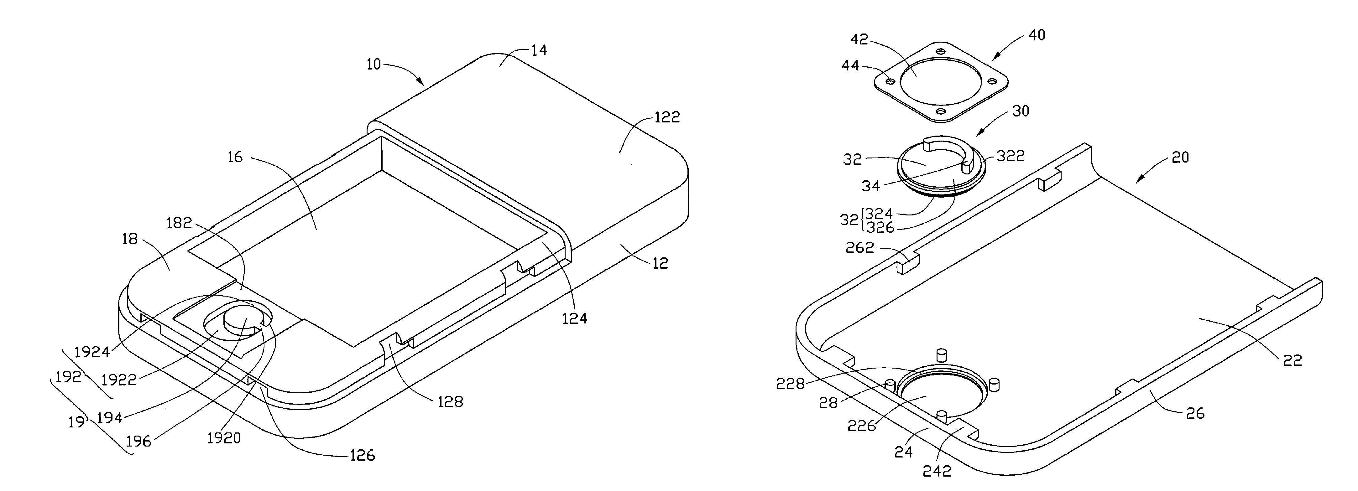
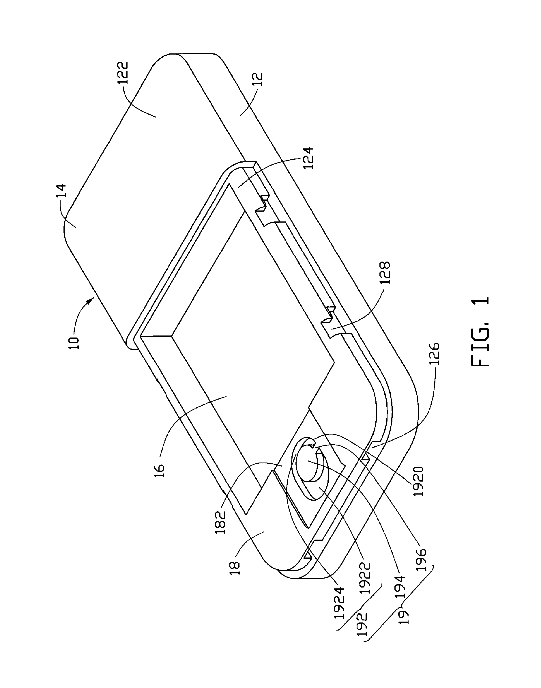
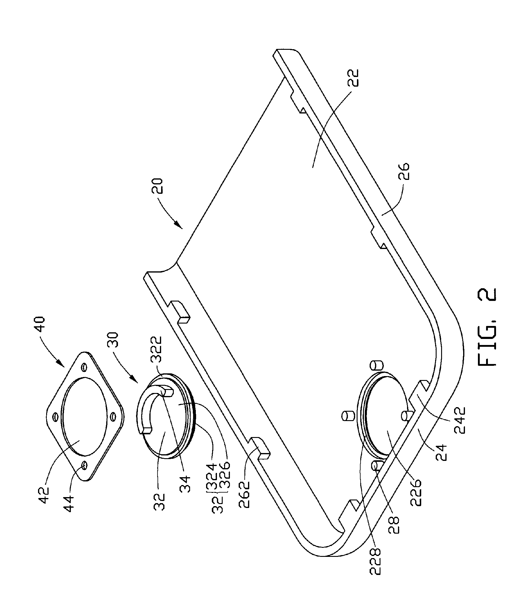
[0015]Referring now to the drawings in detail, FIG. 1 and FIG. 2 show various parts of a battery cover assembly incorporated in a mobile phone / portable electronic device 200 (best seen in any of FIGS. 4-6). The mobile phone 200 is taken here as an exemplary application, for the purposes of describing details of a battery cover assembly of a preferred embodiment of the present invention. The mobile phone 200 includes a housing 10, and a battery cover 20. The battery cover assembly includes the battery cover 20, a locking part 19 defined in the housing 10, a locking member 30, a washer 40, and an engaging mechanism (not labelled). The locking member 30 is rotatably attached to the battery cover 20. Accordingly, the battery cover 20 is engaged with the housing 10 of the mobile phone 200 by means of the locking member 30.

[0016...


PUM

PropertyMeasurementUnit
angleaaaaaaaaaa
sizeaaaaaaaaaa
distanceaaaaaaaaaa

Abstract

A battery cover assembly includes a battery cover (20), a housing (10), and a locking member (30). The battery cover has a receiving hole (16) defined therein. The receiving hole is located proximate to one end of the battery cover. The housing has a locking part (19) defined in one end thereof. The locking part includes a receiving groove (192) and a resisting portion protruding from a bottom of the receiving groove. The locking member has an operating portion (32) and a latching ear (34). The operating portion is rotatably mounted in the receiving hole of the battery cover. The latching ear extends from one side of the operating portion. The latching ear is configured so as to be releasably engageable with the locking part of the housing.

Description

FIELD OF THE INVENTION[0001]The present invention generally relates to battery cover latching assemblies and, more particularly, to a battery cover latching assembly for use in a portable electronic device.DESCRIPTION OF RELATED ART[0002]Batteries are widely used in portable electronic devices, such as personal digital assistants (PDAs), mobile phones, and so on. Conventional batteries are removably received in the electronic device, and battery covers are designed to connect with housings of the electronic devices to package the batteries. The battery has to be replaced by opening the battery cover when, for example, the battery is damaged or dead (e.g., no longer rechargeable).[0003]A clasp structure or latch structure is used with a conventional battery cover, to engage the cover with a housing of a portable electronic device. For example, a typical mobile phone has a latch for the battery cover. The latch includes a pair of hooks at one end of the battery cover, and a locking pi...

Claims


Application Information

Patent Timeline
Patent Type & Authority Patents(United States)
IPC IPC(8): H01R13/64G03B17/04H01M2/10H04M1/00
CPCH01M2/1066Y02E60/10H01M50/209H01M50/00
Inventor TU, YING-LIANGCHEN, CHIA-HUA
Owner FIH (HONG KONG) LTD
Why Eureka
Try Eureka