
Connector structure with a detachable mounting tube

a technology of mounting tube and connector, which is applied in the direction of mechanical equipment, manufacturing tools, couplings, etc., can solve the problems of trouble and waste of money

Inactive Publication Date: 2007-12-11
CHEN BO SHEN
View PDF35 Cites 62 Cited by
  • Summary
  • Abstract
  • Description
  • Claims
  • Application Information

AI Technical Summary

Benefits of technology

[0008]The primary objective of the present invention is to provide a connector structure with a detachable mounting tube, wherein a mounting tube with an inner sliding pipe is detachably secured to an end of a connector. The connector structure can be provided for insertion of the ordinary screwdriver head by the use of the connector, and is also suitable for insertion of the special tool head when the mounting tube is removed from the connector structure.

Problems solved by technology

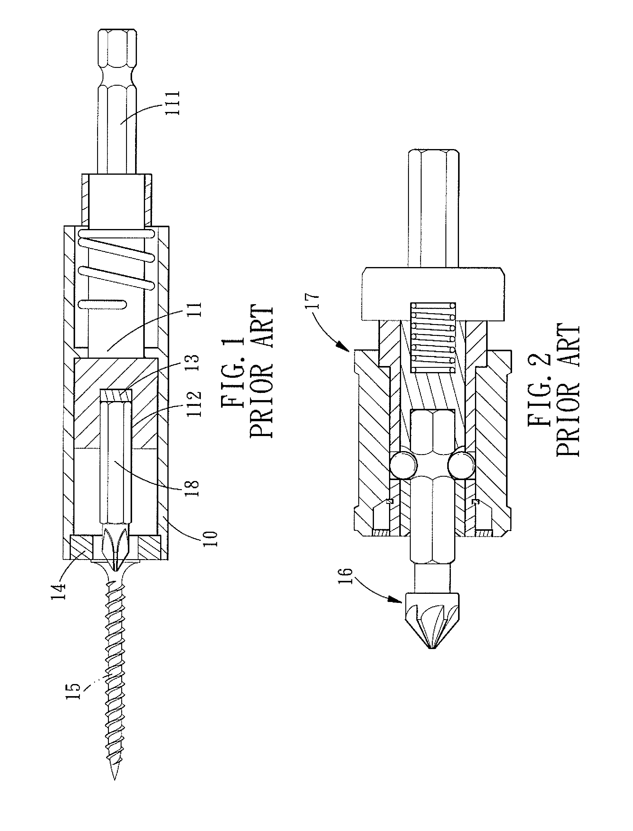
However, as shown in FIG. 2, for a special tool head 16 with a large head and a short length, it must employ another conventional clamping device 17 since the above-mentioned conventional connector structure is not suitable for this special tool head 16.
Therefore, the user has to prepare a clamping device and a connector simultaneously during work, this is not only troublesome but also money wasted.

Method used


Image

  • Connector structure with a detachable mounting tube
  • Connector structure with a detachable mounting tube
  • Connector structure with a detachable mounting tube

Examples


Embodiment Construction

[0019]The present invention will be more clear from the following description when viewed together with the accompanying drawings, which show, for purpose of illustrations only, the preferred embodiment in accordance with the present invention.

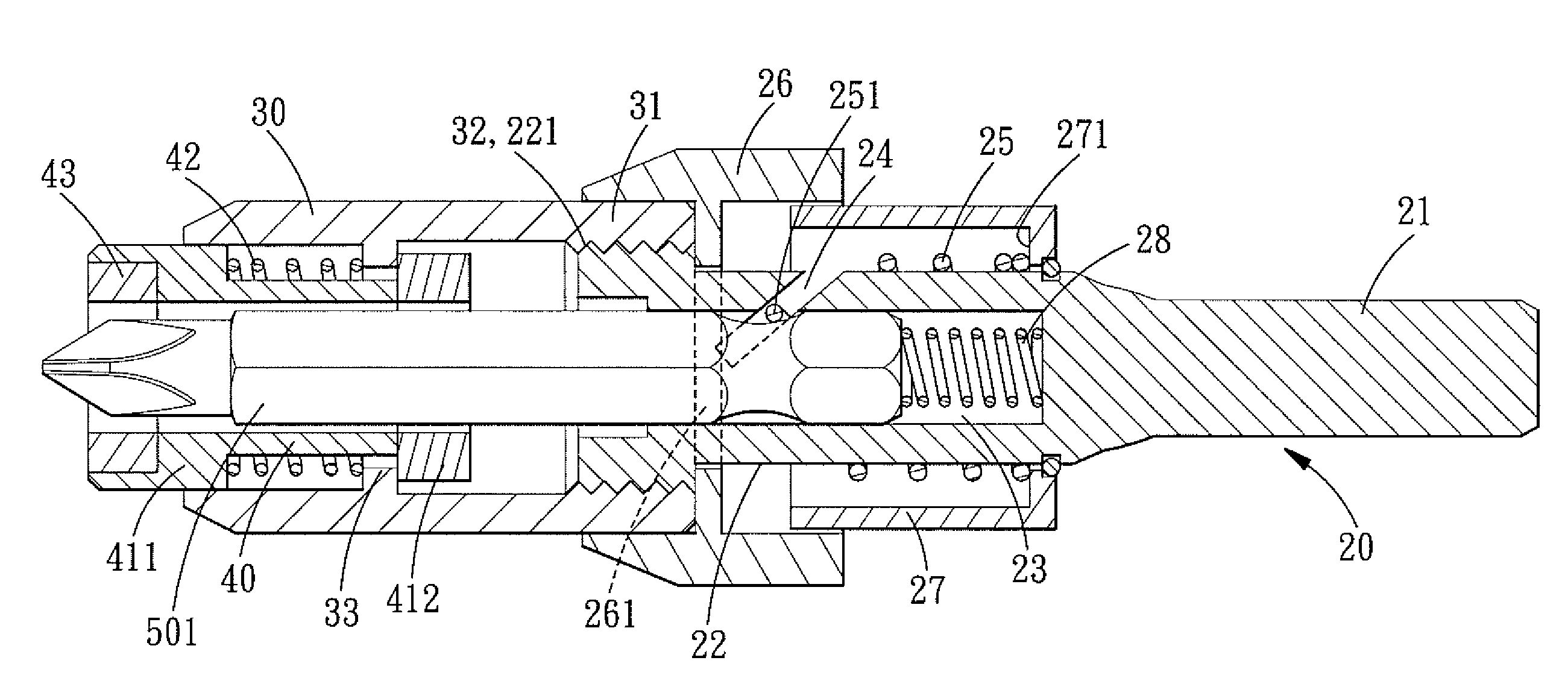
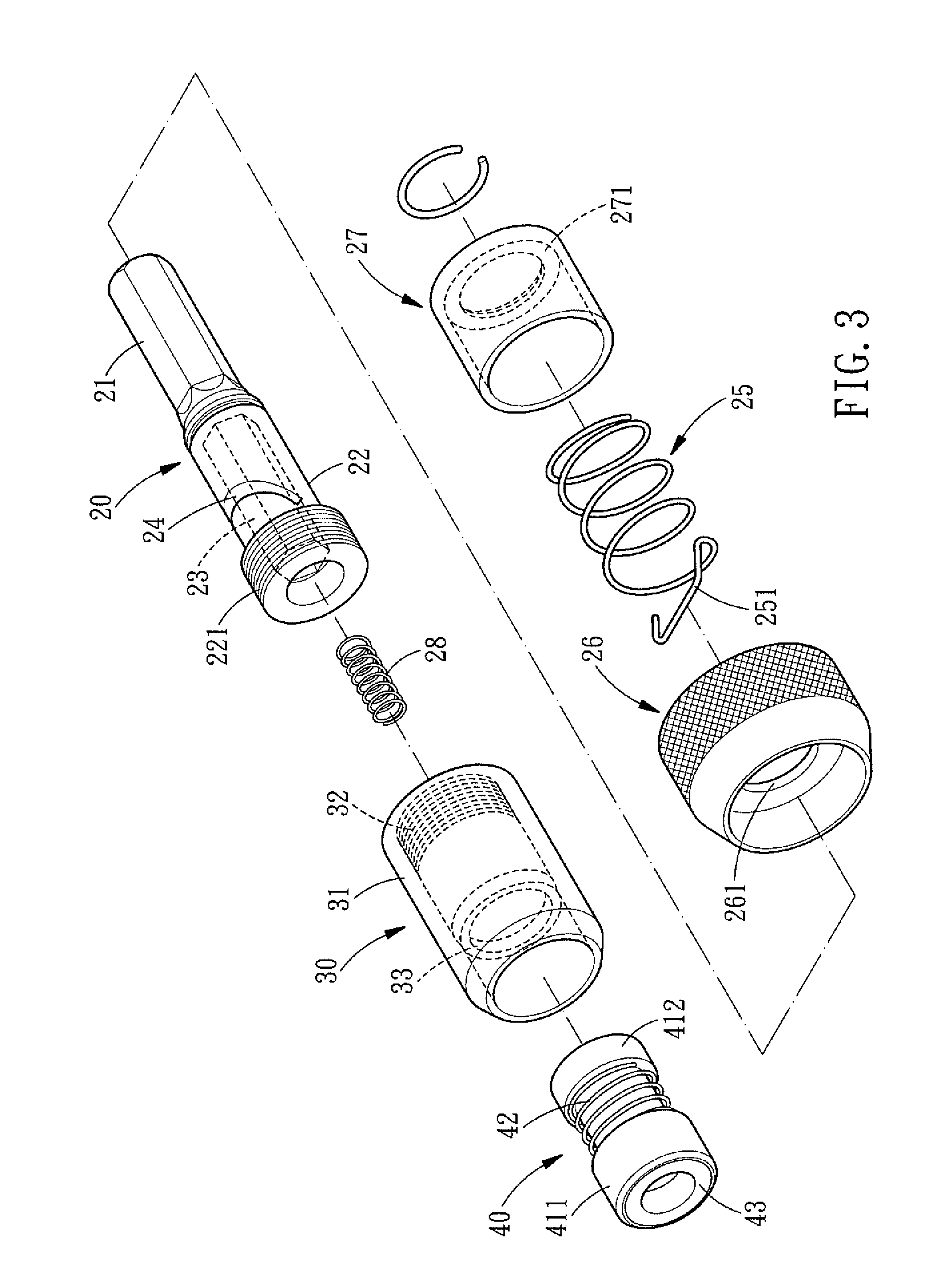
[0020]Referring to FIGS. 3-6, a connector structure with a detachable mounting tube in accordance with a preferred embodiment of the present invention is suitable for insertion of both a screwdriver head 501 and a special tool head 502, and comprises: a connector 20, a mounting tube 30 detachably disposed at an end of the connector 20, and a sliding pipe 40 slideably installed in the mounting tube 30.

[0021]The connector 20 has a coupling end 21 to be coupled to a power tool and has a connecting end 22. A plurality of threads 221 is formed in the outer periphery of the connecting end 22, an inserting hole 23 for insertion of the tool head 502 is formed in the connecting end 22, and the inserting hole 23 can be hexagonal in cross section, so it ...


PUM


Abstract

A connector structure with a detachable mounting tube comprises a mounting pipe with an inner sliding pipe detachably secured to an end of a connector. The connector structure not only can be provided for insertion of an ordinary screwdriver head to carry out screwing and unscrewing operation. Further, when the mounting tube is detached from the connector, a special tool head with a big head and a short length can also be inserted in the connector, thus overcoming the conventional technique bottleneck of needing two different connectors. Besides, the mounting tube is detachable from the connector, for the sake of simplification, the sliding pipe and the mounting tube are integral with each other.

Description

BACKGROUND OF THE INVENTION[0001]1. Field of the Invention[0002]The present invention relates to a connector structure with a detachable mounting tube, and more particularly to a connector structure used on a power tool for insertion of an ordinary screwdriver head or a special tool head.[0003]2. Description of the Prior Art[0004]FIG. 1, (TW Pat. No. 093205513) shows a conventional connector used on a power tool for insertion of screwdriver head, and the connector comprises a shaft 11 slideably installed in a mounting tube 10. The shaft 11 has a connecting end 111 to be coupled to the power tool, and an inserting hole 112 is formed in another end surface of the shaft 11 for insertion of a screwdriver head 12. A first magnetic member 13 is disposed in the bottom of the inserting hole 112, and a second magnetic member 14 is located at the another end of the mounting tube 10. The screwdriver head 18 can be secured in the inserting hole 112 by the magnetic force of the first magnetic me...

Claims


Application Information

Patent Timeline
Patent Type & Authority Patents(United States)
IPC IPC(8): B25G3/18
CPCB25B13/5008B25B15/001B25B23/0035B25B23/0057Y10T279/17743Y10T403/591Y10T279/17811Y10T403/602
Inventor CHEN, BO SHEN
Owner CHEN BO SHEN
Learn More