
Deforming member and captive fastener retaining method

a technology of deformation member and retaining method, which is applied in the direction of screws, fastening means, washers, etc., can solve the problems of inability to re-attach fasteners in high temperature applications, metal clips are impractical for certain applications,

Inactive Publication Date: 2007-12-11
GM GLOBAL TECH OPERATIONS LLC
View PDF111 Cites 62 Cited by
  • Summary
  • Abstract
  • Description
  • Claims
  • Application Information

AI Technical Summary

Benefits of technology

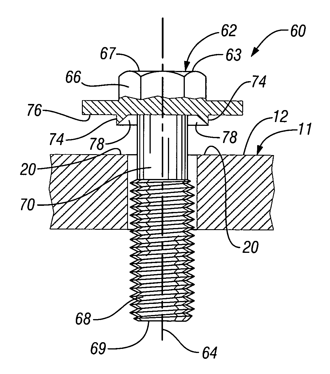
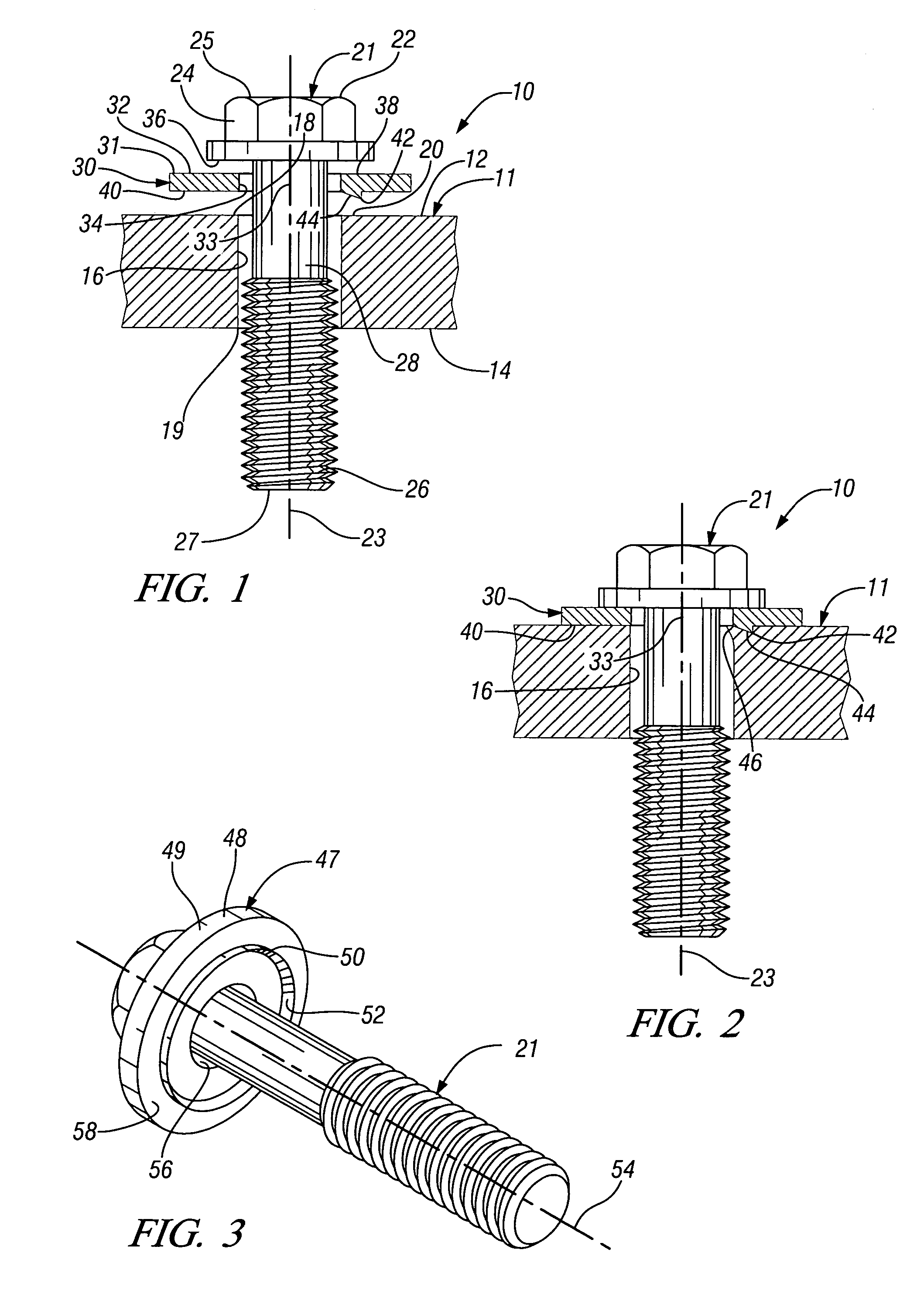
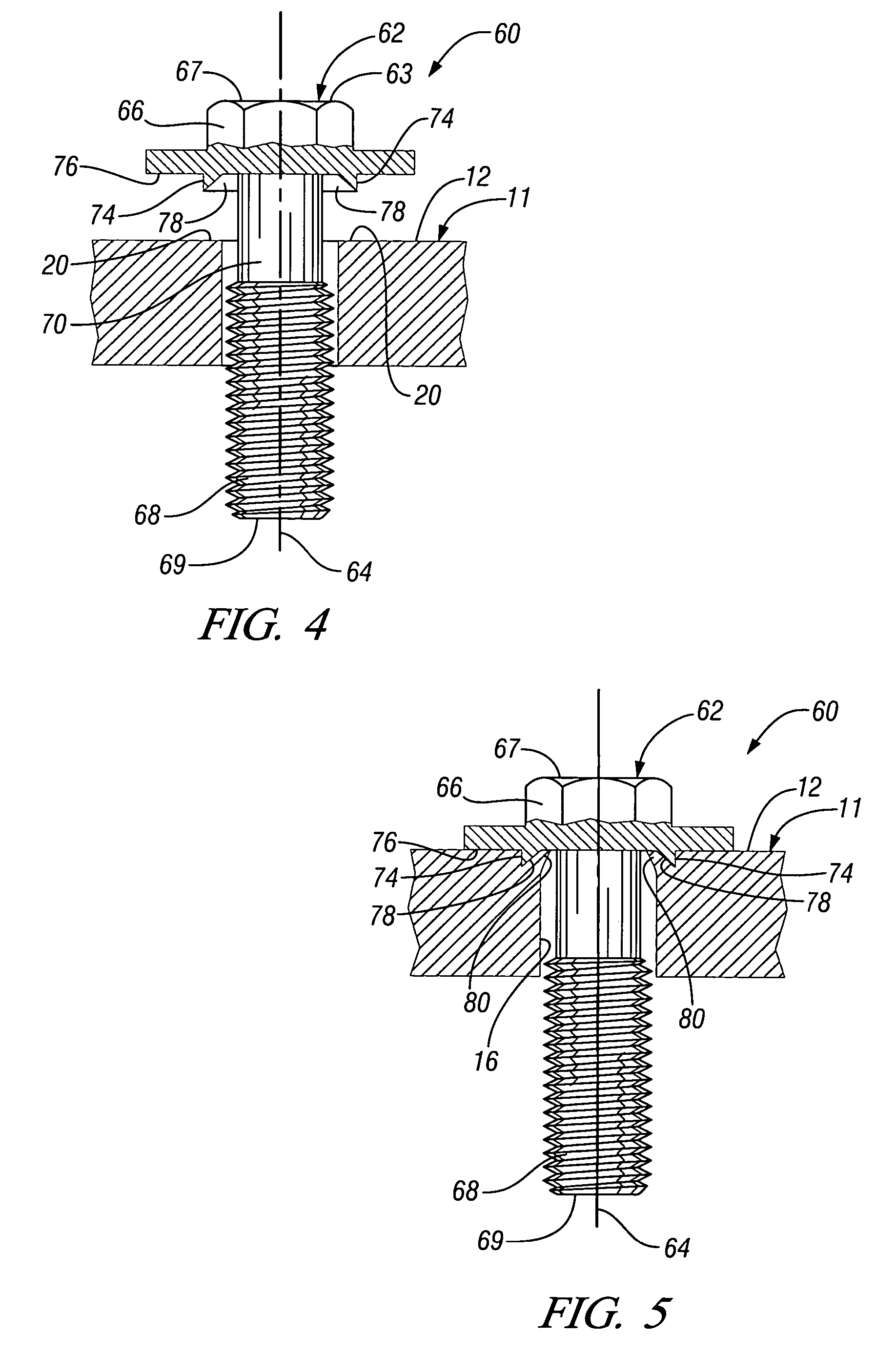
The present invention provides a deforming member for use in retaining a fastener within an opening of a workpiece. The deforming member has a body in the form of a hardened annular washer with a clamping surface and a fastener receiving opening extending through the washer. A wedge-like deforming element extends from the clamping surface and has a deforming face angled radially and axially outward from the axis. The deforming element is configured so that when the deforming element and the clamping surface are pressed against a malleable edge portion of a fastener opening, the wedge deforms at least a portion of the edge into the fastener opening and reduces a diameter of the fastener opening to create a stop which operates to mechanically retain a shank portion of a fastener within the fastener opening. The deforming member may also be integral with a head of a fastener or formed on a reduced diameter portion of the fastener. The technical effect of the invention is to provide a simple and effective solution for securely retaining fasteners in workpieces.

Problems solved by technology

Metal clips are impractical for certain applications.
Elastomer-type retention devices often have low melting or flash points making them unsuitable for retaining fasteners in high temperature applications.

Method used


Image

  • Deforming member and captive fastener retaining method
  • Deforming member and captive fastener retaining method
  • Deforming member and captive fastener retaining method

Examples


Embodiment Construction

[0013]Referring first to FIGS. 1 and 2 of the drawings in detail, numeral 10 generally indicates an assembly including a workpiece 11 adapted to be fastened to another component, not shown. The workpiece 11 may be formed of ductile material and may be in the form of a flange, or a heavier body having upper and lower (or outer and inner) surfaces 12, 14. At least one fastener opening 16 extends through the workpiece 11, between the upper and lower surfaces 12, 14. The fastener opening 16 is further defined by upper and lower edges 18, 19 wherein the upper edge 18 has at least an edge portion 20, which is malleable and able to be deformed. The upper (outer) surface 12 of the workpiece 11 may be flat or otherwise configured, but at least an area of the workpiece extending outward from and generally adjacent to each fastener opening will preferably be essentially flat, without recesses or chambers. Also, the fastener opening area is formed as a unitary one piece component and is free fr...


PUM


Abstract

A fastener is retained within an opening of a workpiece by deforming a portion of an edge of the opening inwardly to prevent removal of the fastener. A deforming member associated with a head of the fastener includes a body having a clamping surface extending radially form a central axis. A wedge-like deforming element has a deforming member and having a deforming face angled axially and radially outward from the clamping surface. The deforming element, when pressed against a malleable edge of the workpiece, deforms at least a portion of the edge into the fastener opening thereby creating a stop which reduces the diameter of the opening and mechanically retains the fastener therein. The deforming member may be formed as a separate washer assembled on the fastener or may be made integral with the fastener head.

Description

TECHNICAL FIELD[0001]This invention relates to captive fasteners and, more particularly, to a deforming member for use in retaining a fastener within an opening of a workpiece.BACKGROUND OF THE INVENTION[0002]Retainable fasteners currently utilize metal clips or elastomer-type retention devices for retaining a fastener within a fastener opening of a workpiece. Metal clips are impractical for certain applications. Elastomer-type retention devices often have low melting or flash points making them unsuitable for retaining fasteners in high temperature applications.SUMMARY OF THE INVENTION[0003]The present invention provides a deforming member for use in retaining a fastener within an opening of a workpiece.[0004]In a first embodiment, the deforming member has a body in the form of a hardened annular washer having a clamping surface extending radially from a central axis and a fastener receiving opening extending through the washer and centered on the central axis. At least one wedge-l...

Claims


Application Information

Patent Timeline
Patent Type & Authority Patents(United States)
IPC IPC(8): F16B21/18F16B39/24F16B39/282
CPCF16B35/065F16B43/00Y10S411/957
Inventor KORNBLUM, STEPHEN R.
Owner GM GLOBAL TECH OPERATIONS LLC
Learn More