AI technical title is built by Patsnap AI team. It summarizes the technical point description of the patent document.
a technology of applied in the field of precision illumination methods and systems, can solve the problems of reducing the number of messages sent to each set of dimmers, requiring special wiring or cabling, and being insufficient for the positioning of mirrors and other mechanical devices, etc., and achieve the effect of limited life span
Inactive Publication Date: 2007-12-11
PHILIPS LIGHTING NORTH AMERICA CORPORATION
View PDF57 Cites 361 Cited by
Summary
Abstract
Description
Claims
Application Information
AI Technical Summary
This helps you quickly interpret patents by identifying the three key elements:
Problems solved by technology
Method used
Benefits of technology
Problems solved by technology
The disadvantage is a reduction in the number of messages sent to each of the set of dimmers, in this example by a factor two.
Normal eight bit messages allow two hundred fifty-six positions, which is inadequate for the positioning of mirrors and other mechanical devices.
A significant problem with present lighting networks is that they require special wiring or cabling.
A second significant problem with present lighting networks is that particular lighting applications require particular lighting types.
Traditional methods of providing pulse width modulated signals include hardware using software programmed timers, which in some instances is not cost effective if not enough timer modules are available, and one interrupt per count processes, in which a microprocessor receives periodic interrupts at a known rate.
The difficulty with the third method is that for multiple PWM channels it is very difficult to arrange the timer based signal updates such that they do not overlap, and then to accurately change the update times for a new value of PWM signals.
Method used
Image
Click on the blue label to locate the original text in one second.
Reading with bidirectional positioning of images and text.
Examples
Embodiment Construction
[0099]The structure and operation of various methods and systems that are embodiments of the invention will now be described. It should be understood that many other ways of practicing the invention herein are available, and the embodiments described herein are exemplary and not limiting.
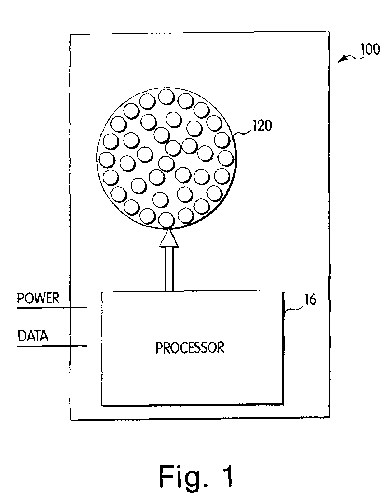
[0100]Referring to FIG. 1, a light module 100 is depicted in block diagram format. The light module 100 includes two components, a processor 16 and an LED system 120, which is depicted in FIG. 1 as an array of light emitting diodes. The term “processor” is used herein to refer to any method or system for processing in response to a signal or data and should be understood to encompass microprocessors, integrated circuits, computer software, computer hardware, electrical circuits, application specific integrated circuits, personal computers, chips, and other devices capable of providing processing functions. The LED system 120 is controlled by the processor 16 to produce controlled illumination. In pa...
PUM
Abstract
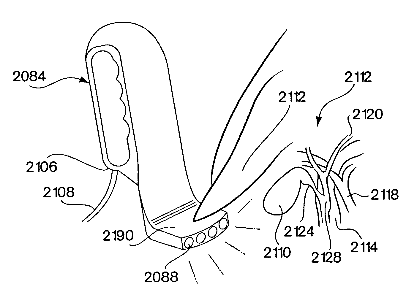
Methods and systems are provided for illuminating body part with LED system. A system includes a LED system, a medical instrument and a microprocessor. The LED system is adapted to generate a variable color radiation. The medical instrument is adapted for positioning the LED system in proximity to the body part to illuminate the body part. The microprocessor is adapted to control at least one electrical current supplied to the LED system to vary a color of the variable color radiation. Exemplary systems may be particularly configured and suitable for use in medical applications, including diagnostic, surgical, forensic, and therapeutic interventions.
Description
CROSS-REFERENCES TO RELATED APPLICATIONS[0001]This application claims the benefit under 35 U.S.C. §120 as a divisional (DIV) of U.S. patent application Ser. No. 09 / 213,189, filed Dec. 17, 1998, entitled “Precision Illumination Methods and Systems,” now U.S. Pat. No. 6,459,919, which application in turn claims the benefit under 35 U.S.C. §120 as a continuation-in-part (CIP) of U.S. patent application Ser. No. 08 / 920,156, filed Aug. 26, 1997, entitled “Multicolored LED Lighting Method and Apparatus,” now U.S. Pat. No. 6,016,038.[0002]Ser. No. 09 / 213,189 also claims the benefit under 35 U.S.C. §119(e) of each of the following U.S. provisional applications:[0003]Ser. No. 60 / 071,281, filed Dec. 17, 1997, entitled “Digitally Controlled Light Emitting Diodes Systems and Methods;”[0004]Ser. No. 60 / 068,792, filed Dec. 24, 1997, entitled “Multi-Color Intelligent Lighting;”[0005]Ser. No. 60 / 078,861, filed Mar. 20, 1998, entitled “Digital Lighting Systems;”[0006]Ser. No. 60 / 079,285, filed Mar. ...
Claims
Application Information
Patent Timeline
Application Date:The date an application was filed.
Publication Date:The date a patent or application was officially published.
First Publication Date:The earliest publication date of a patent with the same application number.
Issue Date:Publication date of the patent grant document.
PCT Entry Date:The Entry date of PCT National Phase.
Estimated Expiry Date:The statutory expiry date of a patent right according to the Patent Law, and it is the longest term of protection that the patent right can achieve without the termination of the patent right due to other reasons(Term extension factor has been taken into account ).
Invalid Date:Actual expiry date is based on effective date or publication date of legal transaction data of invalid patent.

