Method and apparatus for media stream monitoring

Active Publication Date: 2007-12-18
CISCO TECH INC
View PDF4 Cites 250 Cited by
  • Summary
  • Abstract
  • Description
  • Claims
  • Application Information

AI Technical Summary

Problems solved by technology

The problem is that the RTCP reports are only sent between the two gateways in the packet network that are conducting the RTP session and are not available to other network elements that may want to use the reports for policy or billing reasons.

Method used


Image

  • Method and apparatus for media stream monitoring
  • Method and apparatus for media stream monitoring
  • Method and apparatus for media stream monitoring

Examples


Embodiment Construction

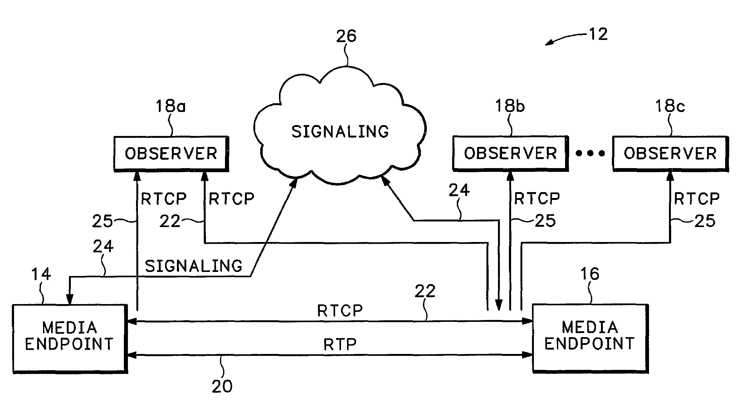
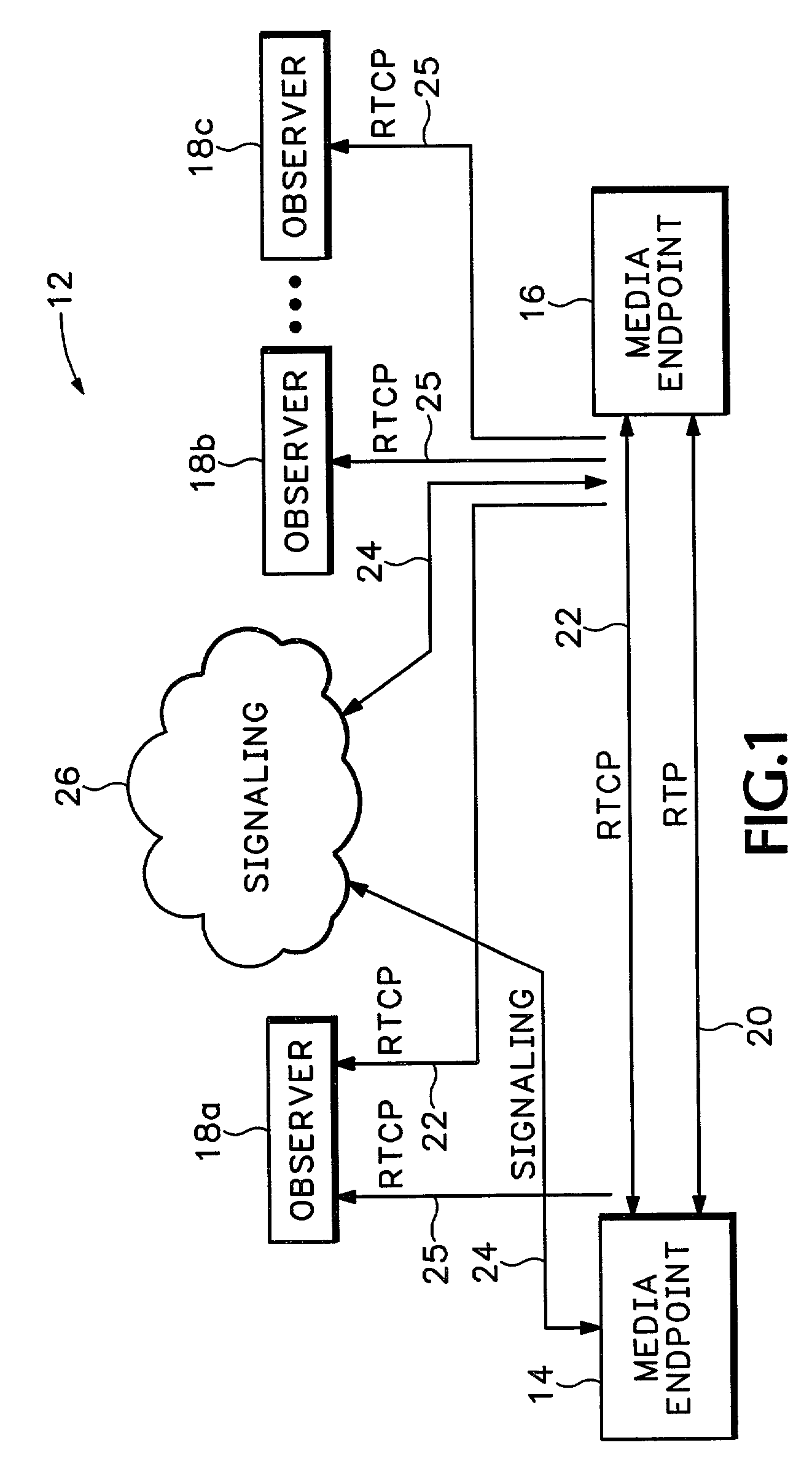
[0011]FIG. 1 shows a packet switched network 12 that includes two media endpoints 14 and 16. The media endpoints 14 and 16 can be any Internet Protocol (IP) phone, Gateway (GW) connected to a Public Switched Telephone Network (PSTN), GW connected to an analog phone, GW connected to any telephony network, or any other device that may need to process audio data.

[0012]A media path 20 is established between the two media endpoints 14 and 16 that carries media data in IP packets. The media path 20 can carry any video, audio or digital data. In one example, a Real Time Protocol (RTP) is used to send the media data between the two media endpoints. The RTP protocol is described in Request For Comment (RFC) 1889 and RFC 1890 which are each herein incorporated by reference. Signaling 24 is conducted through a signaling network 26 to establish the RTP path 20. Examples of protocols used for signaling 24 include H.323, Media Gateway Control Protocol (MGCP), Session Initiated Protocol (SIP), Meg...


PUM


Abstract

A network processing device is signaled to establish a media path with another network processing device in a packet switched network with Session Initiated Protocol (SIP), International Telecommunication Union (ITU) standard H.323, MGCP, Megaco, or some other signaling protocol. The network processing device receives a request to send information to an observer device that is not directly in the media path. The network processing device then sends information about the media path to the observer device.

Description

BACKGROUND[0001]A Voice Over IP (VoIP) call could be directed along a different media path, such as a Public Switched Telephone Network (PSTN), when the IP network carrying the VoIP call is suffering from poor quality. Gateways in the call path could also be notified to use different COmpressor / DECompressors (codecs), etc. when low quality of service is detected in the IP network. A billing system could bill a subscriber at a lower rate when the quality of a call is compromised. Real-time billing data could also be derived if a system could determine the number of bits transmitted or the type of media services used during a packet switched network connection. For example, different billing tables could be used for voice, fax, modem relay, or pass through calls.[0002]Accordingly, different network processing devices, such as call agents, Session Initiated Protocol (SIP) proxies and H.323 gatekeepers, have an interest in monitoring media liveness and heath conditions. H.323 is a stand...

Claims


Application Information

Patent Timeline
Patent Type & Authority Patents(United States)
IPC IPC(8): H04L12/28H04L12/56
CPCH04L29/06027H04L43/087H04L65/80H04L65/1043H04L65/608H04L43/106H04L65/65H04L65/1101
Inventor FITZGERALD, CARYJENNINGS, CULLEN
Owner CISCO TECH INC
Why Eureka
Try Eureka