
Circular knitting-machine chassis with cantilever support

Inactive Publication Date: 2007-12-25
MONARCH KNITTING MACHINERY
View PDF26 Cites 29 Cited by
  • Summary
  • Abstract
  • Description
  • Claims
  • Application Information

AI Technical Summary

Problems solved by technology

Furthermore, in at least one embodiment of the support chassis, the extension assembly is unbalanced about the riser assembly and extends away from the riser assembly in unbalanced cantilever fashion.
Furthermore, in at least one embodiment, the extension assembly is unbalanced about the riser assembly and extends away from the riser assembly in unbalanced cantilever fashion.

Method used


Image

  • Circular knitting-machine chassis with cantilever support
  • Circular knitting-machine chassis with cantilever support
  • Circular knitting-machine chassis with cantilever support

Examples


Embodiment Construction

[0021]The present invention now will be described more fully hereinafter with reference to the accompanying drawings, in which some, but not all embodiments of the invention are shown. Indeed, the invention may be embodied in many different forms and should not be construed as limited to the embodiments set forth herein; rather, these embodiments are provided so that this disclosure will satisfy applicable legal requirements. Like numbers refer to like elements throughout.

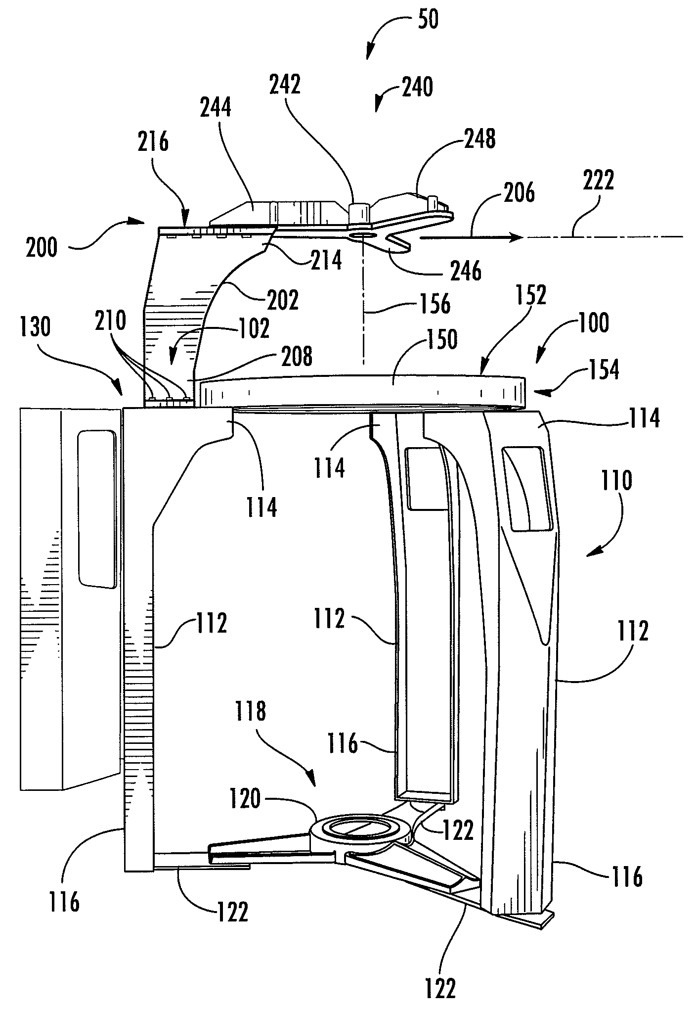
[0022]A novel support chassis 50 according to an embodiment of the invention is illustrated in various stages of assembly in FIGS. 3-6. The support chassis 50 includes a frame assembly 100, a support 200 connected to the frame assembly, and a horizontal ring assembly 300 (FIGS. 5-6). The frame assembly 100 includes a leg assembly 110 and a horizontal bed plate 150 supported by the leg assembly. The support 200 resists bending moments and shear forces and thus defines a cantilever support by entirely supporting the ...


PUM


Abstract

A support chassis for a circular knitting machine includes a frame assembly having a leg assembly and a horizontal bed plate supported by the leg assembly, a support connected to the frame assembly, and a horizontal ring assembly entirely supported by the support in unbalanced cantilever fashion. The support may include a riser assembly and an extension assembly connected to the riser assembly. The extension assembly may be unbalanced about the riser assembly and extend away from the riser assembly in unbalanced cantilever fashion. The support may be connected to the leg assembly independently of the bed plate.

Description

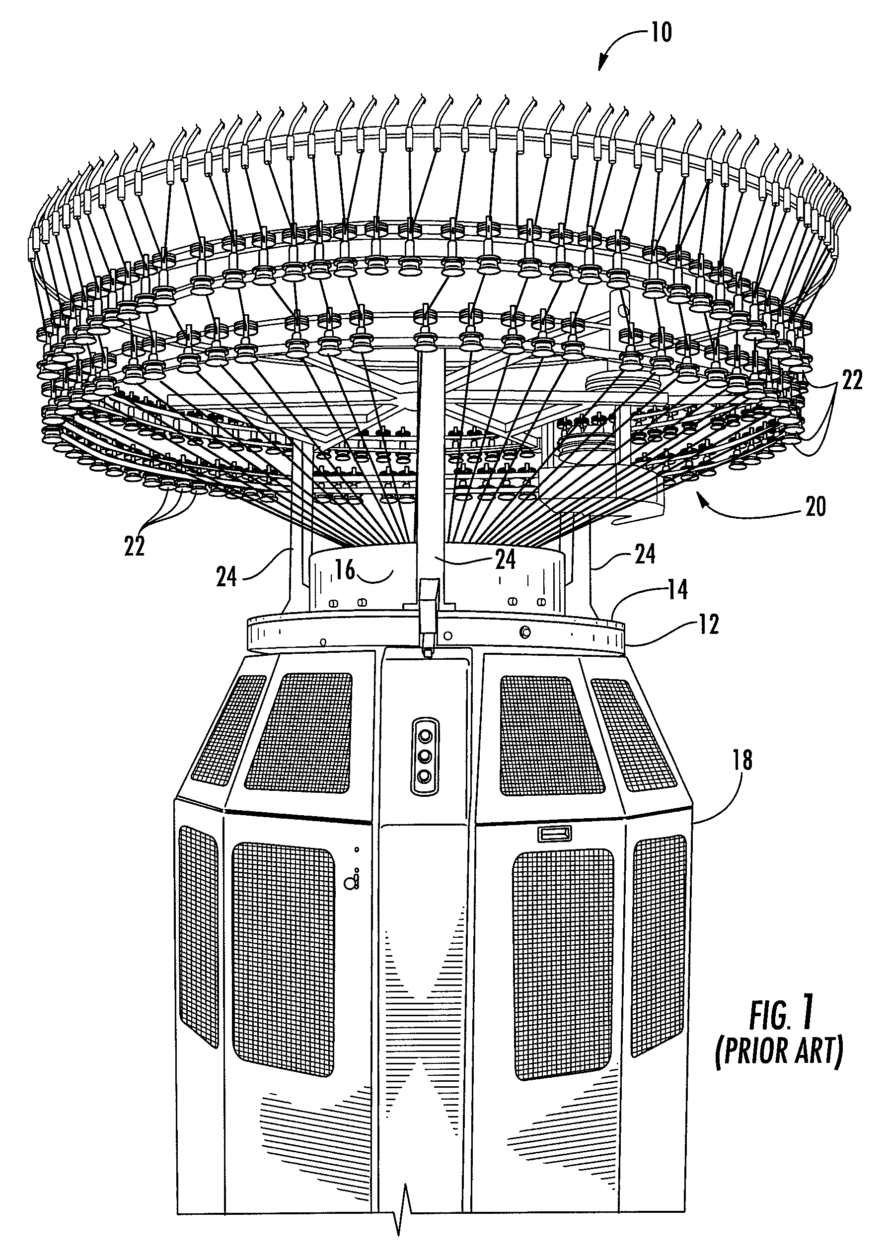
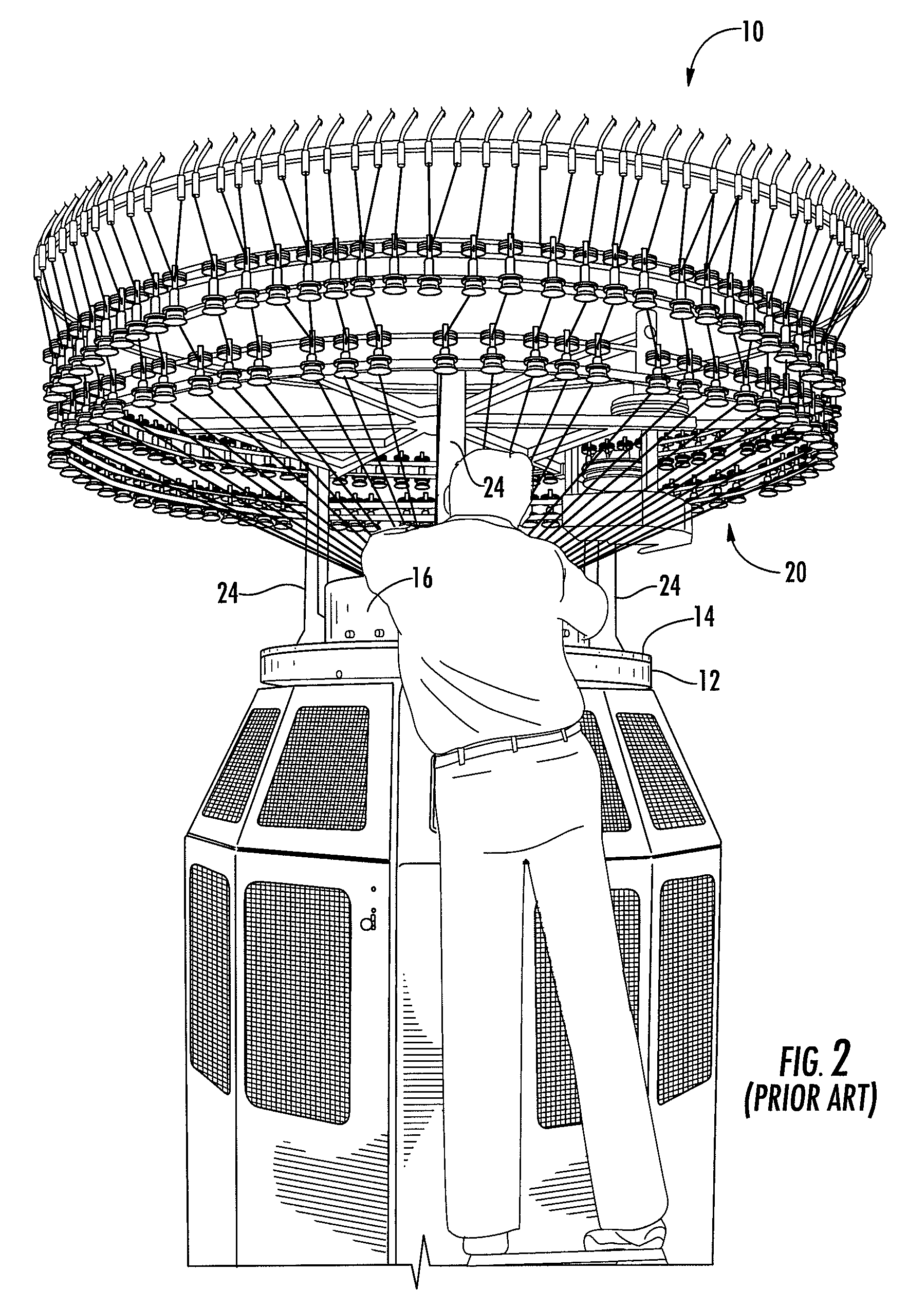
FIELD OF THE INVENTION[0001]Embodiments of the present invention relate generally to circular knitting machines. More particularly, embodiments of the invention relate to a support chassis for a circular knitting machine wherein a cantilever support bears a ring assembly.BACKGROUND OF THE INVENTION[0002]A circular knitting machine 10 according to the prior art is shown in FIG. 1. The circular knitting machine 10 comprises a raised horizontal bed plate 12 that supports a cam-retaining ring 14. A revolving gear ring rotatably supported by a ball race resides between the cam-retaining ring and the bed plate. A knitting cylinder surrounded by a cylindrical cover assembly 16 supports knitting elements such as pivoting cams and reciprocating needles that are actuated by the revolving gear ring when the machine 10 is operated to produce tubular knitted fabric. The fabric passes down through the knitting cylinder and bed plate as knitting proceeds and is generally collected on a roll that r...

Claims


Application Information

Patent Timeline
IPC IPC(8): D04B9/00
CPCD04B15/38D04B9/00
Inventor RENDA, JAMES A.
Owner MONARCH KNITTING MACHINERY
Learn More