Split core sensing transformer

a transformer and split-core technology, applied in the direction of transformer/inductance details, inductance modifications, inductances, etc., can solve the problems of difficult installation of branch power conductors in distribution panels, bulky hinges, and difficult installation of close-spaced wires

Active Publication Date: 2007-12-25
VERIS INDS
View PDF8 Cites 266 Cited by
  • Summary
  • Abstract
  • Description
  • Claims
  • Application Information

AI Technical Summary

Problems solved by technology

While the hinged split core sensing transformer permits encirclement of a connected power cable, the hinge is bulky and installation on the closely spaced, branch power conductors in a distribution panel can be difficult.

Method used


Image

  • Split core sensing transformer
  • Split core sensing transformer
  • Split core sensing transformer

Examples


Embodiment Construction

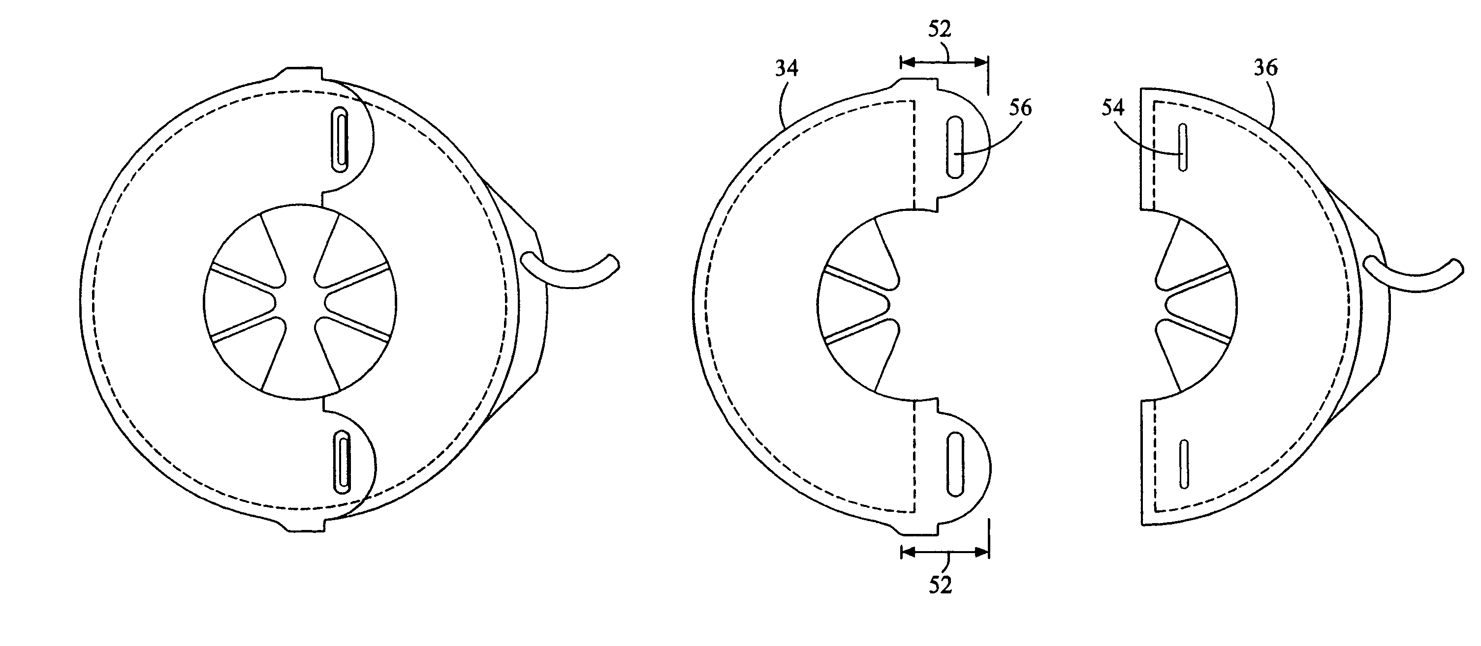
[0021]Referring in detail to FIGS. 1-7 where similar parts of the invention are identified by like reference numerals, a sensing transformer 20 comprises a magnetically permeable toroidal core 22 that substantially encircles a power conductor 26 that is connected to conduct an electrical current to be measured. The core 22 is a ferrous torus typically having a rectangular or circular cross-section. One or more turns of wire 28 are wrapped around the cross-section of a sector 24 (indicated by a bracket) of the toroidal core 22.

[0022]A changing current (i.e. alternating current) in a power conductor produces a changing magnetic field around the conductor which, in turn, induces a magnetic flux in the magnetically permeable core of a sensing transformer encircling the power conductor. The magnetic flux in the toroidal core induces a current in the wire windings that is representative of the current flowing in the power conductor. Thus, the power conductor is the primary winding and the...


PUM

PropertyMeasurementUnit
depthaaaaaaaaaa
diameteraaaaaaaaaa
diameteraaaaaaaaaa

Abstract

Separable toroidal segments reduce the size of a sensing transformer that can be installed on an electrical conductor while connected to a device.

Description

[0001]This application claims the benefit of U.S. patent application Ser. No. 60 / 586,303 filed Jul. 7, 2004.STATEMENT REGARDING FEDERALLY SPONSORED RESEARCH OR DEVELOPMENT[0002]Not applicable.CROSS-REFERENCE TO RELATED APPLICATIONS[0003]Not applicable.BACKGROUND OF THE INVENTION[0004]The present invention relates to devices for sensing electrical current and, more particularly, to a split core sensing transformer for a current sensor.[0005]It is often desirable to monitor power consumption in the individual branch circuits of a facility as well as the overall energy usage by the facility. Individual branch circuit monitoring not only permits billing for energy consumption by the various consumers, but permits billing to be extended to take into account low power factors or high total harmonic distortion, promoting efficiency by allowing the operator of the facility to determine whether and where capital investment for power quality enhancement equipment would provide the best return...

Claims


Application Information

Patent Timeline
Patent Type & Authority Patents(United States)
IPC IPC(8): H01F27/28
CPCH01F38/30H01F27/263H01F3/10H01F30/16G01R1/22
Inventor BRUNO, DAVID
Owner VERIS INDS
Why Eureka
Try Eureka