
Method and apparatus for sensing and controlling residual mass on customer images

a residual mass and image technology, applied in electrographic process apparatus, instruments, optics, etc., can solve the problems of limited information provided by measuring residual mass with a point sensor like an etac, limited information provided by typical etac sensors, and limited transfer performance, etc., to achieve the effect of improving print quality performance and stability

Active Publication Date: 2007-12-25
XEROX CORP
View PDF8 Cites 9 Cited by
  • Summary
  • Abstract
  • Description
  • Claims
  • Application Information

AI Technical Summary

Benefits of technology

The patent text describes a system and method for improving the quality and stability of printing in a xerographic engine. The system includes a residual mass sensor that can detect and record the residual toner mass levels on a surface after the transfer process. This allows for closed-loop control of the transfer system and monitoring of changes in the residual mass over time. The sensor can identify transfer defects and provide information to adjust the system for optimal performance. The technical effect of this system is improved print quality and stability.

Problems solved by technology

The information provided by measuring the residual mass with a point sensor like an ETAC is limited to an average measurement of transfer performance.
In addition, because a point sensor typically only measures the transfer efficiency at one isolated location in the cross-process direction, variations that occur across the photoreceptor or transfer belt are not detected by this type of sensor.
Therefore, typical ETAC sensors provide only minimal or “gross” information that is employed to control transfer performance.
However, prior methods were still only concerned with measuring average transfer efficiency.
Thus, although the residual mass per unit area value obtained may be more sensitive or accurate than prior point sensors (because it averages over a larger area), such sensing systems do not fully utilize the information that is available from the optical sensor.

Method used


Image

  • Method and apparatus for sensing and controlling residual mass on customer images
  • Method and apparatus for sensing and controlling residual mass on customer images
  • Method and apparatus for sensing and controlling residual mass on customer images

Examples


Embodiment Construction

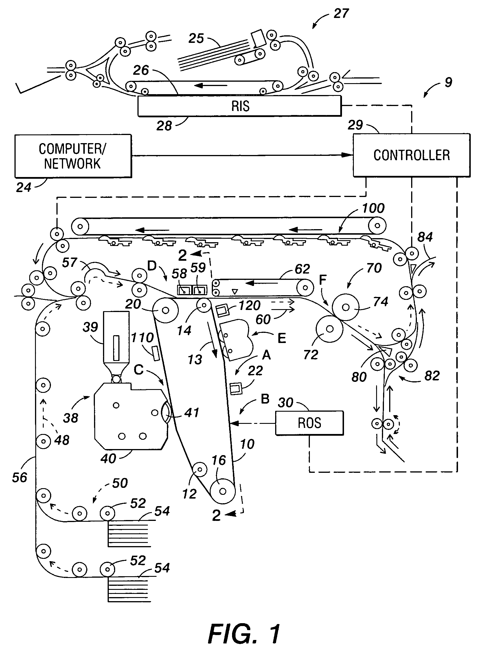
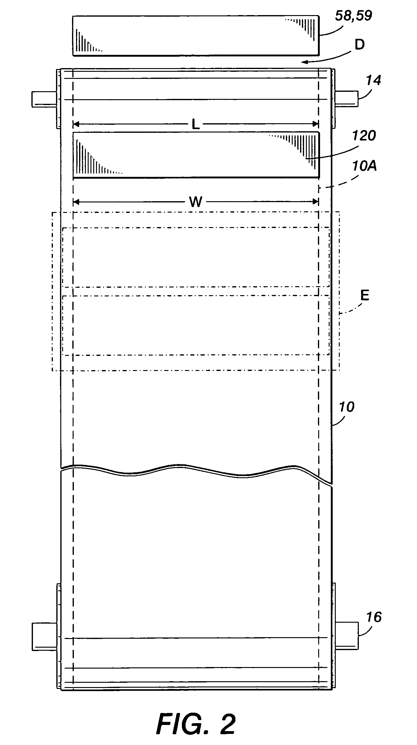
[0018]For a general understanding of the features of the disclosed system and method, reference is made to the drawings, which are for purposes of illustration and are not representative of size or scale. In the drawings, like reference numerals have been used throughout to identify identical elements.

[0019]When examining transfer performance by sensing the residual mass on a photoreceptor, prior methods utilized residual mass sensing and a suitable closed-loop control system to optimize transfer efficiency (or average residual mass levels) in the xerographic system. Because of the inability to discern between various types of transfer related defects, these prior methods were not completely effective at controlling the output of the transfer process. For example, to correct a problem with transfer induced point deletions, the transfer field would typically be reduced. However, to correct a problem with transfer induced mottle, the transfer field would typically be increased. As it ...


PUM


Abstract

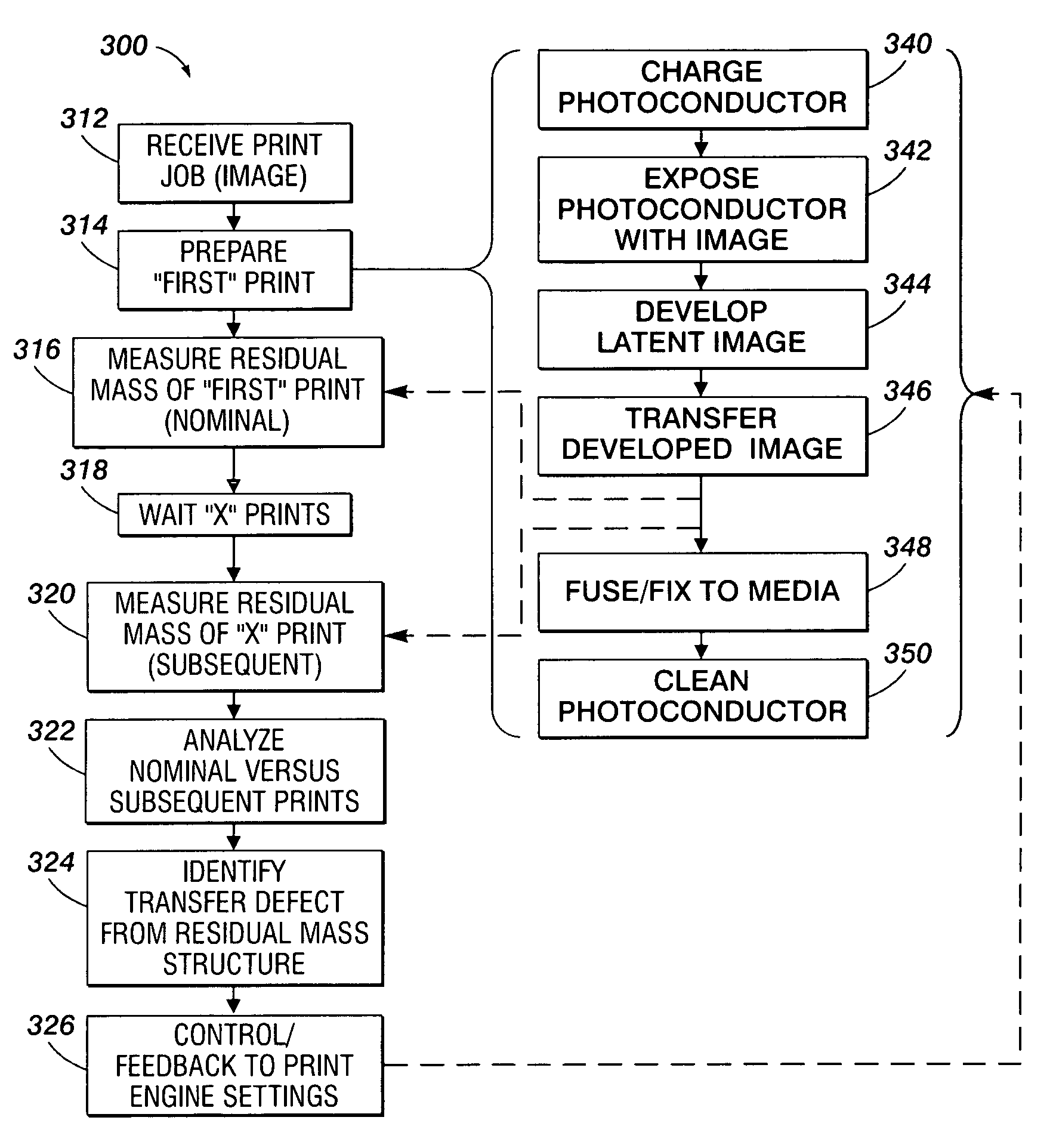
Disclosed is a method and apparatus for sensing residual toner mass after transfer of a xerographic image, to facilitate the identification and characterization of different types of transfer defects. The technique employed utilizes a nominal residual mass signature, measured at the start of a job, in conjunction with subsequent residual mass signature, where the calculated difference between the nominal and subsequent signatures is used to indicate transfer defects and changes in transfer efficiency.

Description

CROSS-REFERENCE TO RELATED APPLICATIONS[0001]U.S. patent application Ser. No. 11 / 094,454, for a FULL-WIDTH ARRAY SENSING OF TWO-DIMENSIONAL RESIDUAL MASS STRUCTURE TO ENABLE MITIGATION OF SPECIFIC DEFECTS, filed Mar. 31, 2005 by Aaron M. Burry et al. is hereby incorporated by reference in its entirety.[0002]A method and apparatus is disclosed for sensing residual mass after transfer of a xerographic image, to facilitate the identification and characterization of different types of transfer defects. The technique employed utilizes a nominal residual mass per unit area (RMA) measured at the start of a job in conjunction with subsequent residual mass per unit area measurements, where the calculated difference between the nominal and follow-up residual mass per unit area is used to indicate transfer defects—such as a loss of transfer efficiency in a particular region of a document.BACKGROUND AND SUMMARY[0003]As disclosed in U.S. Pat. No. 5,887,221 to Grace; and U.S. Pat. No. 5,543,896 t...

Claims


Application Information

Patent Timeline
Patent Type & Authority Patents(United States)
IPC IPC(8): G03G15/00
CPCG03G15/1645G03G15/5041G03G2215/1609G03G2215/00042
Inventor BURRY, AARON M.FLETCHER, GERALD M.HAMBY, ERIC S.PAUL, PETER
Owner XEROX CORP
Learn More