Electrical power connector

a technology of electrical power connectors and connectors, applied in the direction of flexible/turnable line connectors, coupling contact members, coupling device connections, etc., can solve the problems of difficult to reduce the size of arrangements without adversely affecting heat dissipation capabilities, and provide only minimal flexibility to change contact normal forces

Inactive Publication Date: 2008-01-01
FCI AMERICAS TECH LLC
View PDF86 Cites 48 Cited by
  • Summary
  • Abstract
  • Description
  • Claims
  • Application Information

AI Technical Summary

Problems solved by technology

Such arrangements are difficult to reduce in size without adversely effecting heat dissipation capabilities.
They also provide only minimal flexibility to change contact normal forces by adjustment of contact geometry.

Method used


Image

  • Electrical power connector
  • Electrical power connector
  • Electrical power connector

Examples


Embodiment Construction

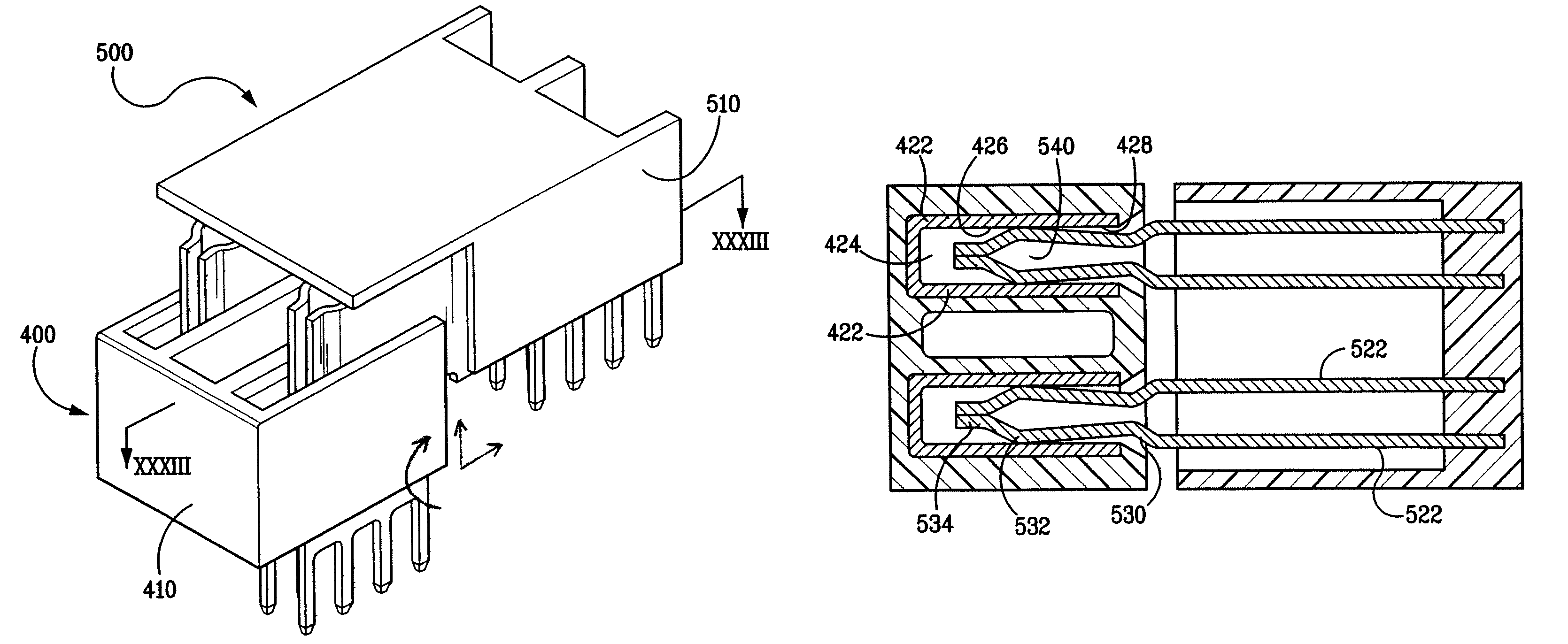
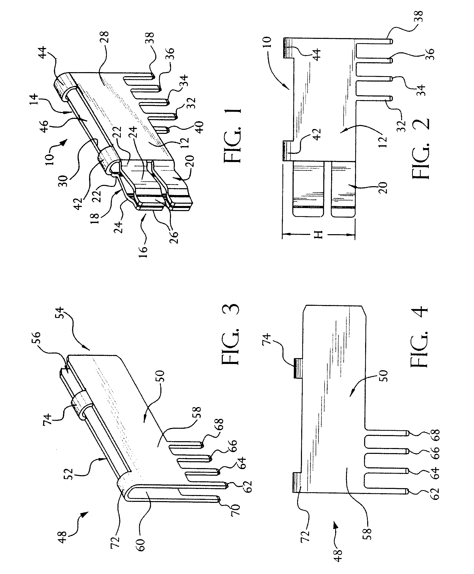
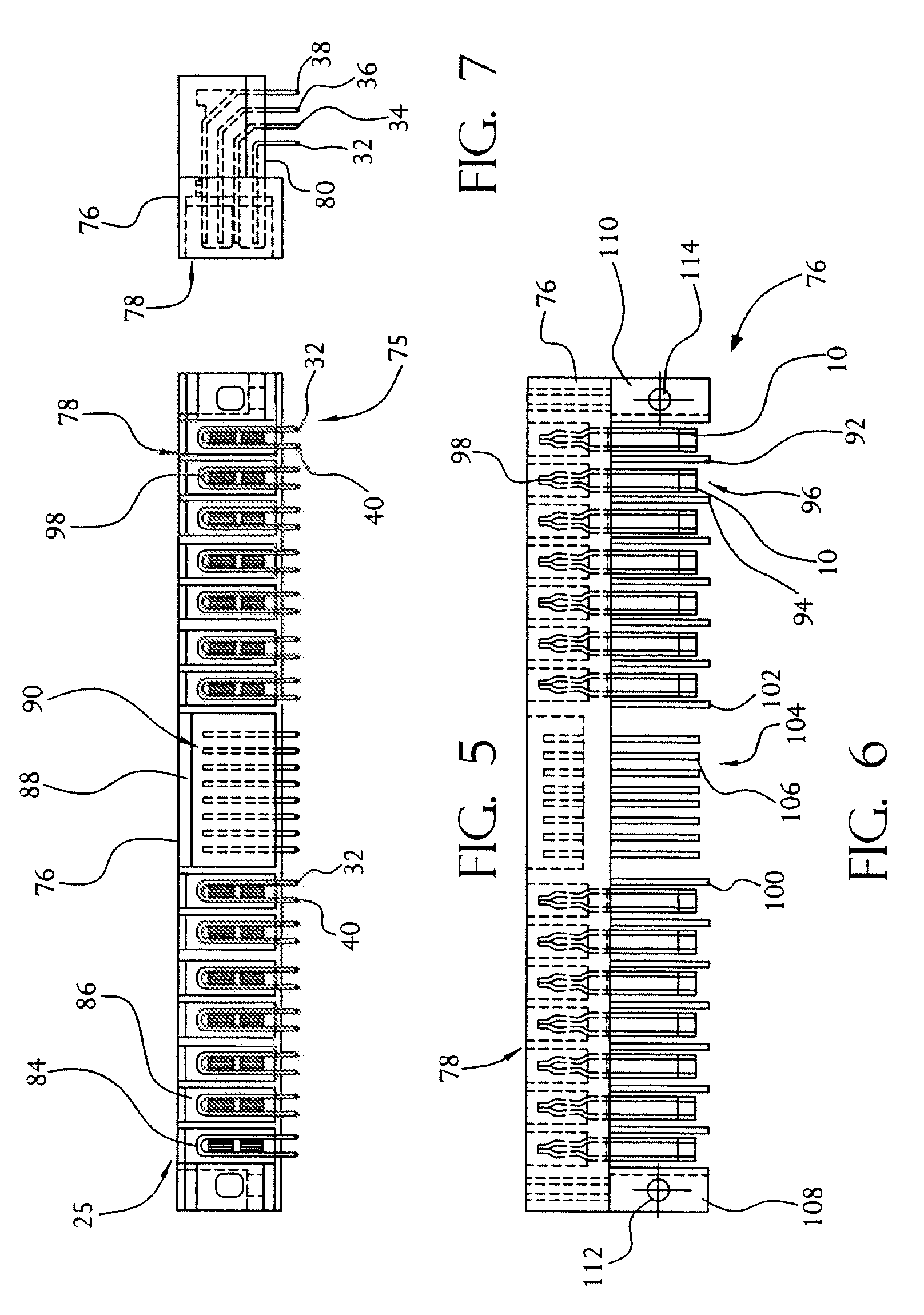
[0043]Referring to FIGS. 1 and 2, a plug contact 10 for use in a plug connector is shown. This plug contact has two opposed major side walls 12 and 14. A front projection, identified generally by numeral 16, has an upper section 18 and a lower section 20. Each of these upper and lower sections comprises a pair of opposed cantilever beams, each beam having inwardly converging proximal section 22, arcuate contact section 24 and a distal section 26. The opposed distal sections 26 are preferably parallel to each other. The distal sections can be positioned slightly apart when the beams are in relaxed condition, but come together when the beams are deflected as the front projection is inserted into a receptacle contact (as explained below). This provides over-stress protection for the beams during mating. The side walls also include planar panels 28 and 30. Terminals 32, 34, 36 and 38 extend from an edge of panel 28. Terminal 40 extends from panel 30, along with a plurality of like termi...


PUM


Abstract

A pair of mating connectors includes a receptacle having an insulative housing and at least one conductive receptacle contact with a pair of spaced walls forming a plug contact receiving space. The plug connector has an insulative housing and at least one conductive contact having a projection engageable in the plug receiving space of the receptacle contact. The open structure of both the receptacle and plug contacts enhances heat dissipation and allows flexibility in achieving desired contact normal forces. The contact construction is especially useful for electronic power connectors.

Description

CROSS REFERENCE TO RELATED APPLICATIONS[0001]This application is a continuation-in-part of U.S. patent application Ser. No. 09 / 886,432, filed Jun. 21, 2001, now U.S. Pat. No. 6,869,294, which is a continuation of U.S. patent application Ser. No. 09 / 160,900, filed Sep. 25, 1998, which is now U.S. Pat. No. 6,319,075, and which claims the benefit of United States Provisional Patent Application Ser. No. 60 / 082,091, filed Apr. 17, 1998; the contents of all of which are incorporated by reference herein.FIELD OF THE INVENTION[0002]The present invention relates to electrical connectors and more particularly to electronic power connectors especially, useful in circuit board or backplane interconnection systems.BACKGROUND OF THE INVENTION[0003]Designers of electronic circuits generally are concerned with two basic circuit portions, the logic or signal portion and the power portion. In designing logic circuits, the designer usually does not have to take into account any changes in electrical p...

Claims


Application Information

Patent Timeline
Patent Type & Authority Patents(United States)
IPC IPC(8): H05K1/00
CPCH01R12/777H01R12/778H01R12/727H01R12/7088H01R35/04
Inventor NORTHEY, WILLIAM A.BROWN, III, JOHN B.CLARK, STEPHEN L.ORTEGA, JOSEPH L.SHUEY, JOSEPH B.
Owner FCI AMERICAS TECH LLC
Why Eureka
Try Eureka