

FEXT cancellation of mated RJ45 interconnect
a technology of rj45 and interconnection, applied in the field of network testing, can solve the problem of not reaching the maximum cancellation of any given parameter, and achieve the effect of canceling the signal components of the fext signal
- Summary
- Abstract
- Description
- Claims
- Application Information
AI Technical Summary
Benefits of technology
Problems solved by technology
Method used
Image

Examples
Embodiment Construction
[0015]The system according to a preferred embodiment of the present invention comprises an implementation of a test instrument for performing test and measurement operations.
[0016]The invention provides an improved test instrument that effectively cancels FEXT signal components at the instrument connector. Reflected energy from the link-under-test is coupled into the receiving signal path by FEXT occurring in the instrument connector. The “reflected FEXT” energy component is an error component in the NEXT measurement of the link.
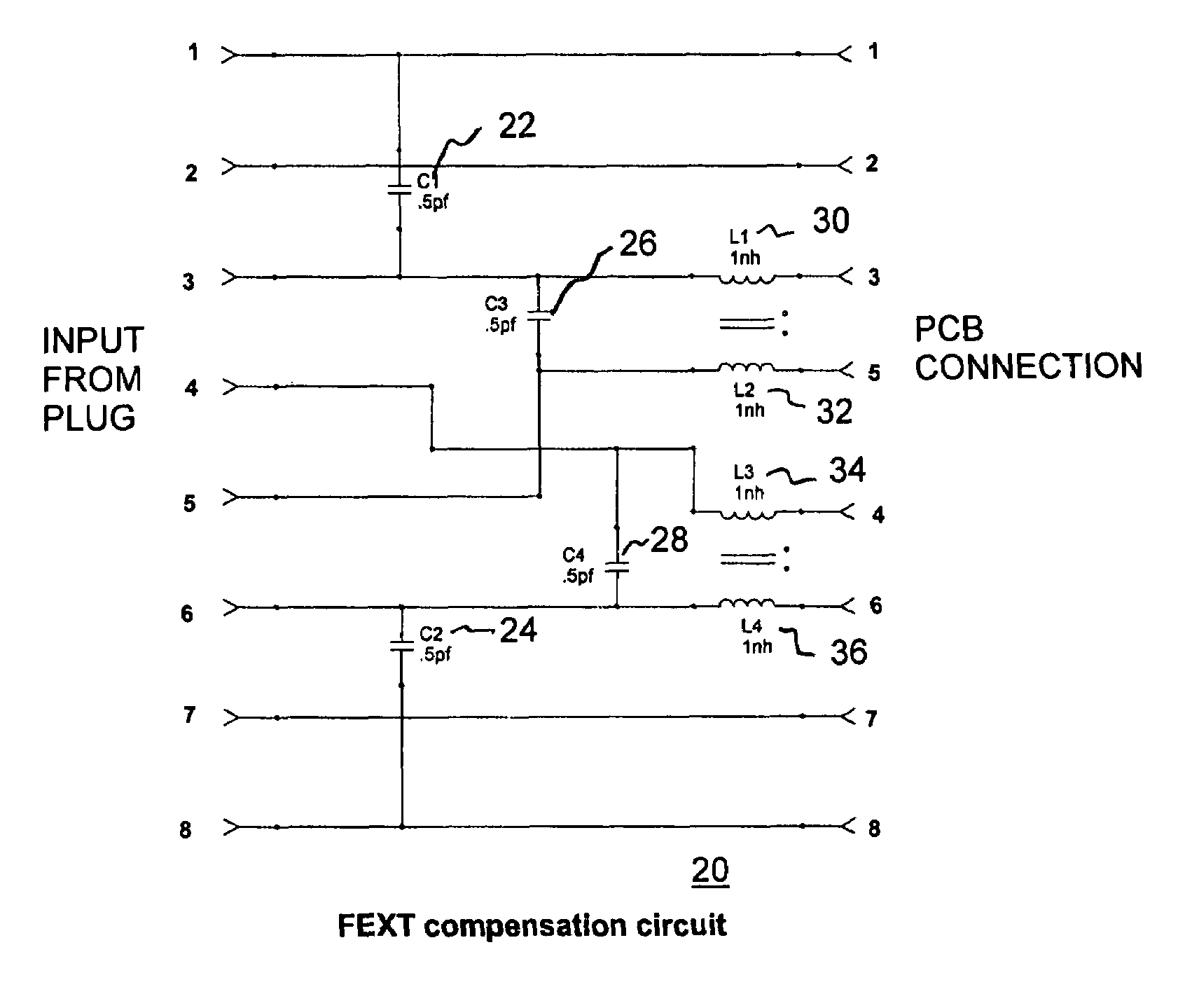
[0017]Referring to FIG. 4, a circuit diagram of an FEXT compensation circuit in accordance with the invention, the preferred embodiment of the invention is implemented in a test and measurement instrument for use with networking. The instrument has an RJ45 jack therein to receive a corresponding RJ45 plug, to connect to a network cable. In order to minimize FEXT, a compensation circuit 20 is provided. In FIG. 4, the compensation circuit is described with res...
PUM
 Abstract
Description
Claims
Application Information