Layered film fabrication method, layered film defect detection method, layered film defect detection device, layered film, and image display device

a technology of defect detection and fabrication method, applied in the direction of optical radiation measurement, instruments, polarizing elements, etc., can solve the problem that the defect inspection of the polarizing plate cannot be accurately performed, and achieve the effect of satisfactory accuracy and efficient canceled shift in retardation

Inactive Publication Date: 2009-11-26
NITTO DENKO CORP
View PDF5 Cites 17 Cited by
  • Summary
  • Abstract
  • Description
  • Claims
  • Application Information

AI Technical Summary

Benefits of technology

[0019]According to such configuration, the shift in retardation can be efficiently canceled. The orientation angle variation indicates the retardation variation in the film surface, and is an, index representing the extent of shift from the desired orientation direction (orientation angle) of molecules for controlling the retardation of the optical compensation layer. The present invention can be preferably applied in the layered film including the optical compensation layer used in the final product such as the image display device and the layered film including the optical compensation layer which orientation angle variation is controlled to smaller than or equal to 4°, whereby inspection of satisfactory accuracy can be performed. The orientation angle variation is obtained by measuring the orientation angle at about three to six points equally in the width direction of the film, and determining the difference between the maximum value and the minimum value, wherein the orientation angle can be measured with a commercially available retardation measurement apparatus such as KOBRA-21ADH manufactured by Oji Keisoku Co.
[0020]Preferably, the optical compensation layer according to the present invention includes a discotheque liquid crystal layer, and the inspection retardation filter is an inspection discotheque liquid crystal layer having the same characteristics. The shift in retardation thus can be thus efficiently canceled.

Problems solved by technology

As a result, the defect inspection of the polarizing plate cannot be accurately performed.

Method used


Image

  • Layered film fabrication method, layered film defect detection method, layered film defect detection device, layered film, and image display device
  • Layered film fabrication method, layered film defect detection method, layered film defect detection device, layered film, and image display device
  • Layered film fabrication method, layered film defect detection method, layered film defect detection device, layered film, and image display device

Examples


Embodiment Construction

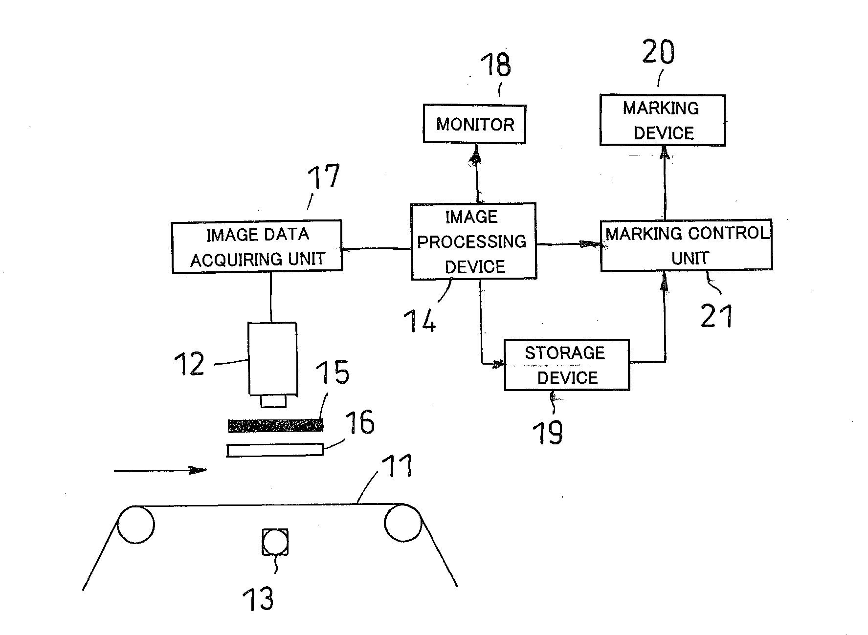
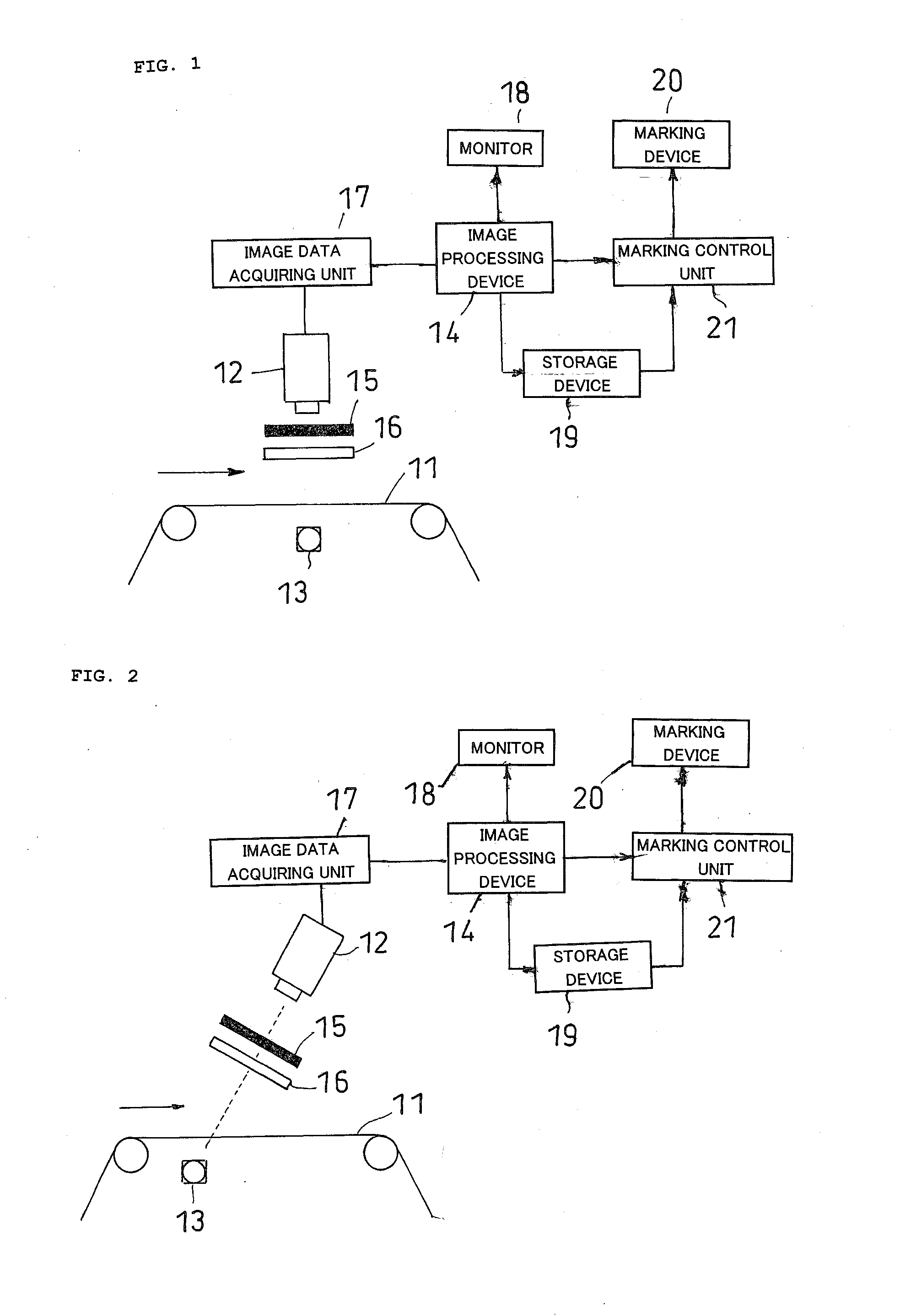
[0052]Suitable embodiments of layered film defect detection method and device according to the present invention will now be described with reference to the figures. FIG. 1 is a schematic view showing a configuration of the defect detection method and device. As shown in FIG. 12, a layered film 11 to be inspected is configured by at least a polarizing plate 1 and an optical compensation layer to be layered on the polarizing plate 1. Retardation film and orientation liquid crystal layer are listed as the optical compensation layer.

[0053]In FIG. 1, the layered film 11 is pulled out from a state wound to a roll (not shown), and conveyed from the left side to the right side of the figure. A light source 13 for inspection is arranged on one side (lower side in FIG. 1) of a film surface of the layered film 11. The light source 13 may be fluorescent lamp, halogen lamp, metal halide lamp, LED, or the like, and the appropriate light source 13 is selected depending on the type of layered film...


PUM

PropertyMeasurementUnit
orientation angleaaaaaaaaaa
widthaaaaaaaaaa
lengthaaaaaaaaaa

Abstract

When inspecting a defect of a layered film having a polarizer by using an inspection polarizing filter or an inspection phase difference filter, members to be arranged in the imaging optical path are arranged in an appropriate order. A defect detection method of a layered film (11) having a polarizing plate (1) and an optical compensation layer includes: a step of applying light from a light source arranged at the polarizing plate layer side of the film surface of the layered film (11); a step of imaging a transmitting light image of the layered film (11) by an imaging unit (12) arranged at the optical compensation layer side of the film surface; and a defect detection step for detecting a defect existing on the layered film (11) according to the transmitting light image captured by the imaging unit (12). The imaging unit (12) performs imaging via an inspection polarizing filter (15) arranged on the optical path between the light source (13) and the imaging unit (12) and adjacent to the imaging unit (12); and an inspection phase difference filter (16) arranged on the optical path between the light source (13) and the imaging unit (12) and between the inspection polarizing filter (15) and the layered film (11).

Description

TECHNICAL FIELD[0001]The present invention relates to a fabrication method of a layered film in which at least a polarizing plate and an optical compensation layer are layered, a layered film defect detection method, a layered film defect detection device, a layered film, and an image display device.BACKGROUND ART[0002]The layered film in which a retardation film (corresponding to optical compensation method) is layered on a polarizing plate via an adhesive layer is known as a layered film of the present invention. A layered configuration example of the layered film is shown in FIG. 12. A layered film 11 is configured by a polarizing plate 1 including a polarizer 1a and a protective film 1b layered on both sides thereof via an adhesive layer, and a retardation film 2 (or retardation layer directly layered on one side of the polarizing plate 1) layered on one side of the polarizing plate 1 via an adhesive layer 2a. When inspecting defects such as foreign substances, scratches, nicks ...

Claims


Application Information

Patent Timeline
Patent Type & Authority Applications(United States)
IPC IPC(8): G01J4/00B32B37/00
CPCG01N21/21G01N21/896G01N21/8422G01M11/00G02B5/30
Inventor KOBAYASHI, TAKAMASAHAGIWARA, MICHIHIROYANO, YUUKISHIZEN, KOUJI
Owner NITTO DENKO CORP
Why Eureka
Try Eureka