
Headset to provide noise reduction

a headset and noise reduction technology, applied in the field of headsets, can solve the problems of not providing practical noise control performance, too large noise generated by the mri in the process of obtaining an image of an affected part of a patient, and sound field, so as to achieve the effect of reducing the impact on the user

Inactive Publication Date: 2014-10-23
SAMSUNG ELECTRONICS CO LTD
View PDF3 Cites 17 Cited by
  • Summary
  • Abstract
  • Description
  • Claims
  • Application Information

AI Technical Summary

Benefits of technology

The present disclosure provides a headset with a noise control system that can effectively isolate and cancel out high levels of noise while protecting the patient's auditory ear drum. The headset includes a cushion to reduce impact and block external noise before reaching the blocking unit. This is helpful to create a comfortable and safe environment for patients during MRI scans.

Problems solved by technology

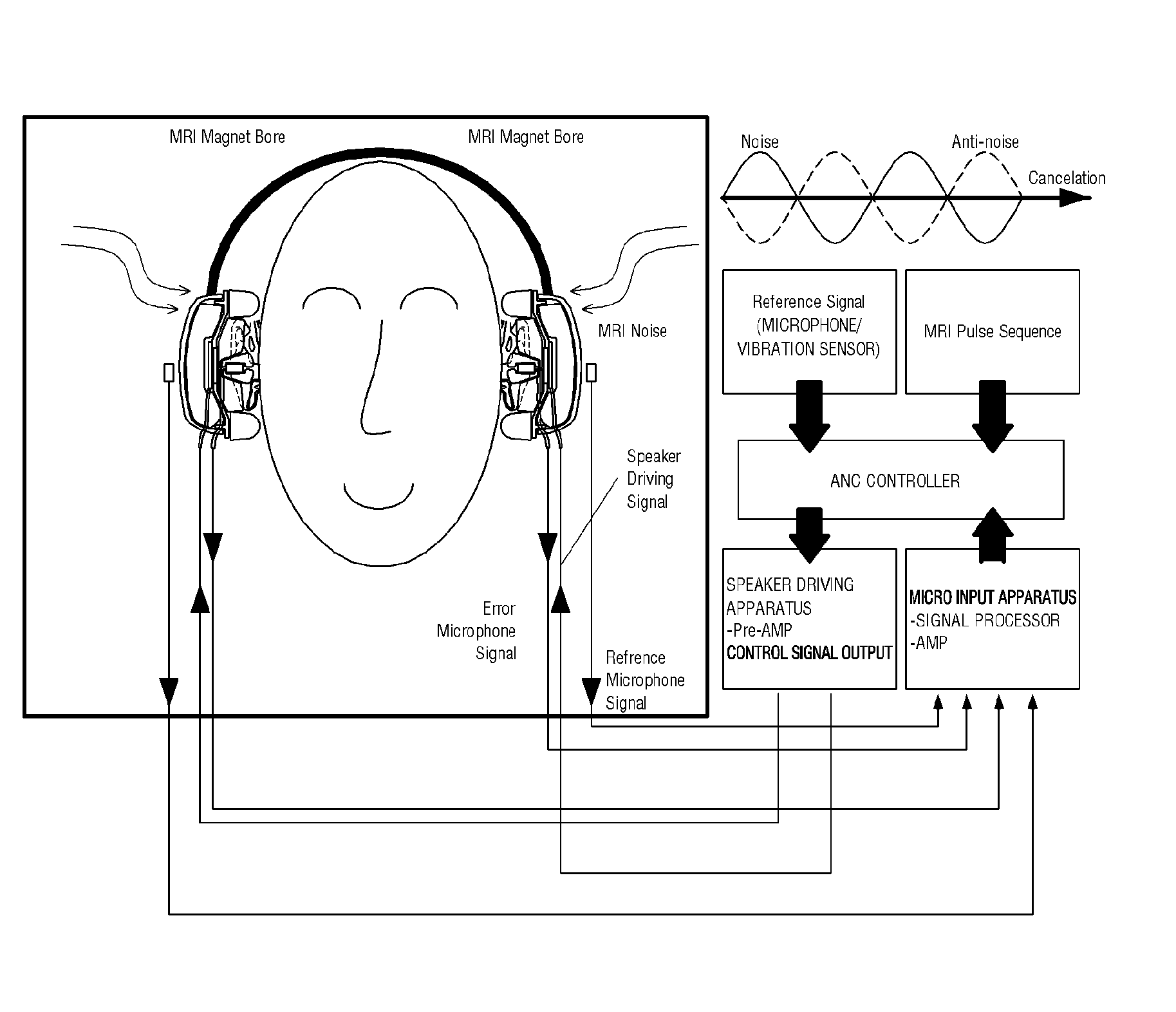
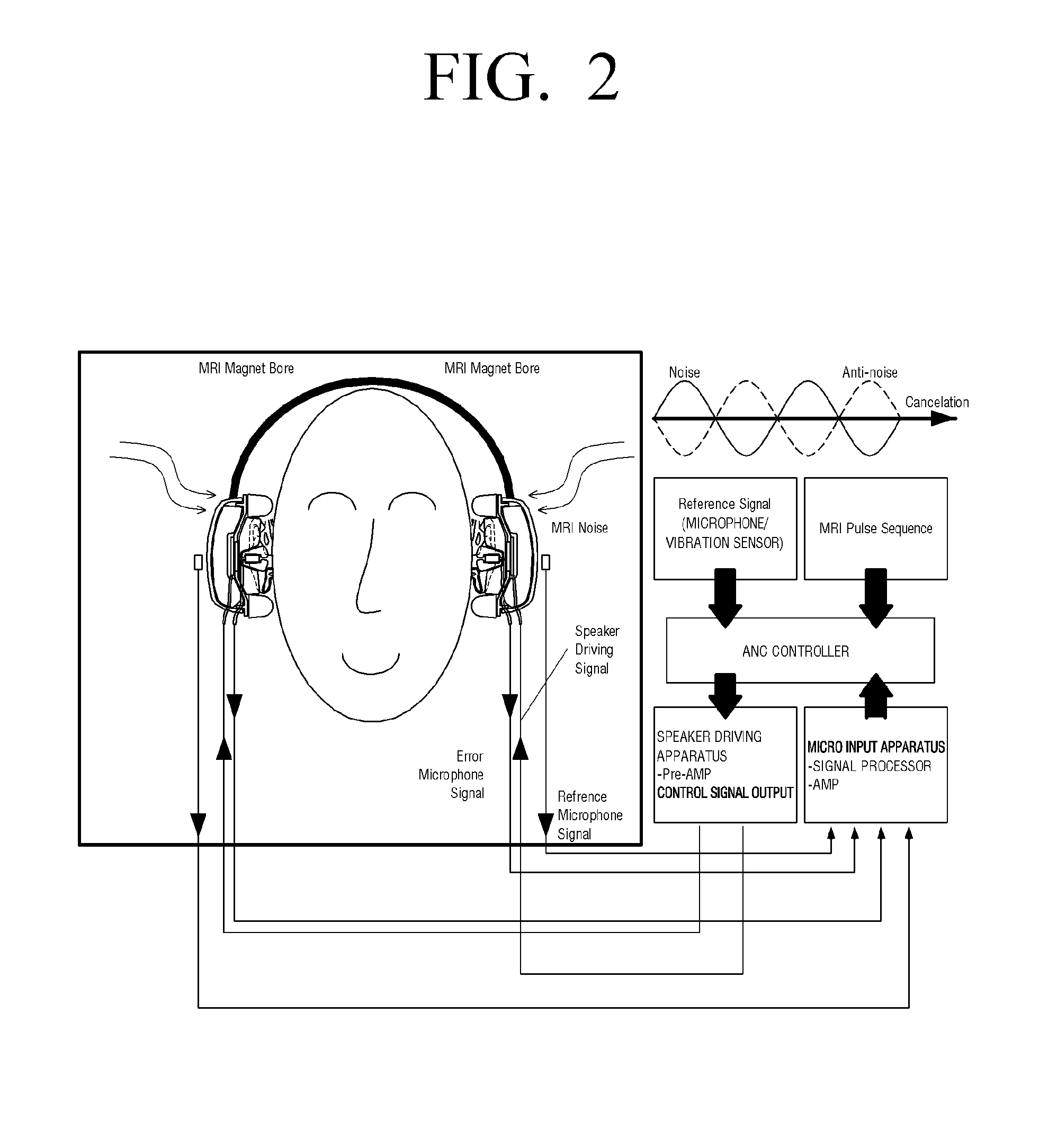
However, there is a problem that noise being generated using the MRI in a process of obtaining an image of an affected part of a patient is too large.
Alternatively, the method blocks a noise source itself by using materials to prevent vibration of the MRI equipment itself (a main cause of the MRI noise).
However, a sound field control by an external speaker or a method to transmit sound generated by the external speaker to the inside of the headset through a tube, which was used as a conventional active control method, causes sound field disturbance and signal delay, thereby not providing practical noise control performance.
Also, since a microphone is positioned at a distance from a human ear so as not to control actual noise inside the ear, the amount of noise to be canceled is limited while high-frequency noise cannot be canceled.
Also, although a headset type of speaker and microphone are used, locations of the speaker and microphone are varied depending on each of users wearing the headset or each time of wearing the headset by a user so that transfer paths between the speaker and the ear and between the microphone and the ear are unstable.

Method used


Image

  • Headset to provide noise reduction
  • Headset to provide noise reduction
  • Headset to provide noise reduction

Examples


Embodiment Construction

[0039]Hereinafter, certain exemplary embodiments of the present disclosure will be described in detail with reference to the accompanying drawings.

[0040]The matters defined herein, such as a detailed construction and elements thereof, are provided to assist in a comprehensive understanding of this description. Thus, it is apparent that exemplary embodiments may be carried out without those defined matters. Also, well-known functions or constructions are omitted to provide a clear and concise description of exemplary embodiments. Further, dimensions of various elements in the accompanying drawings may be arbitrarily increased or decreased for assisting in a comprehensive understanding.

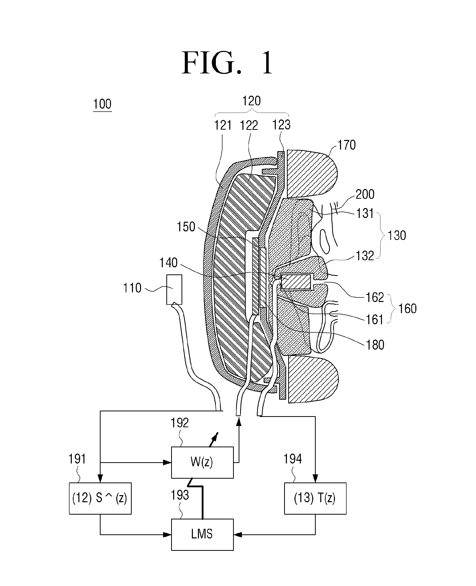
[0041]FIG. 1 is a sectional view illustrating a structure of a headset according to an embodiment of the present disclosure.

[0042]Referring to FIG. 1, a headset 100 according to an embodiment of the present disclosure includes a first microphone 110, a first blocking unit 120, a second blocking unit 130...


PUM


Abstract

A headset to provide noise reduction may include a first microphone that is disposed outside the headset and detects external noise, a first blocking unit configured to block the external noise entering an inside of the headset, a second blocking unit configured to block external noise which is not blocked by the first blocking unit, a second microphone configured to detect internal noise of the headset including noise which is not blocked by the first blocking unit and the second blocking unit, and a speaker configured to output canceling noise to cancel the internal noise detected by the second microphone, wherein the second blocking unit surrounds the second microphone and comprises a one-way sound transmitting passage.

Description

CROSS-REFERENCE TO RELATED APPLICATIONS[0001]This application claims the benefit under 35 U.S.C. §119(a) from Korean Patent Application No. 2013-0043726 filed Apr. 19, 2013 in the Korean Intellectual Property Office, the disclosure of which is incorporated herein by reference in its entirety.BACKGROUND OF THE INVENTION[0002]1. Field of the Invention[0003]The present disclosure relates to a headset, and more particularly, to a headset to provide noise reduction that can protect hearing by effectively blocking external noise by using an active noise control method and a passive noise control method.[0004]2. Description of the Related Art[0005]In the modern medical related field, importance of imaging equipment is increasing day by day. Hospitals are utilizing equipment such as an X-ray, computerized tomography (CT), a magnetic resonance imaging apparatus (MRI), etc., in order to diagnose and treat patients' illness more quickly and accurately. Various laboratories are utilizing equipm...

Claims


Application Information

Patent Timeline
Patent Type & Authority Applications(United States)
IPC IPC(8): H04R3/00G01R33/28A61F11/14
CPCH04R3/002A61F2011/145G01R33/288A61F11/14H04R1/1008H04R1/1083H04R2460/01G01R33/283G10K2210/1081G10K2210/1161G10K2210/3224G10K11/17861G10K11/17881H04R1/10
Inventor LEE, GUN-WOOKO, SANG-CHULLEE, YOUNG-SANGKIM, YOUNG-TAE
Owner SAMSUNG ELECTRONICS CO LTD
Learn More