Adjusting mechanism for a prosthetic

a technology of adjusting mechanism and prosthesis, which is applied in the field of prosthetics, can solve the problems of large size, complex structure, and general cost of manufactur

Inactive Publication Date: 2008-01-15
THERMAL TECH
View PDF4 Cites 51 Cited by
  • Summary
  • Abstract
  • Description
  • Claims
  • Application Information

AI Technical Summary

Problems solved by technology

A variety of adjustable prosthesis joints are known; however, they are generally expensive to manufacture, complex and larger than desirable.

Method used


Image

  • Adjusting mechanism for a prosthetic
  • Adjusting mechanism for a prosthetic
  • Adjusting mechanism for a prosthetic

Examples


Embodiment Construction

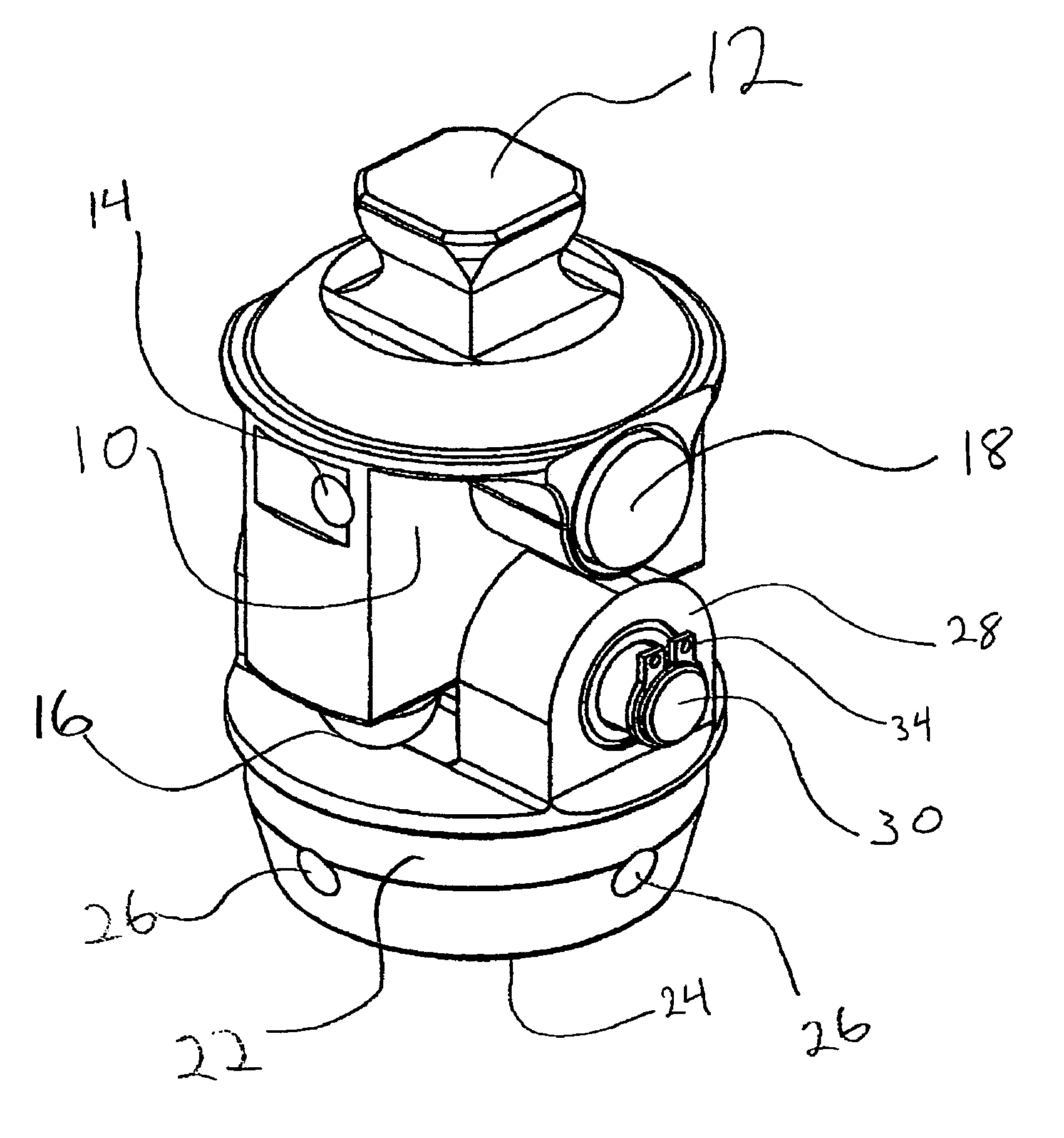
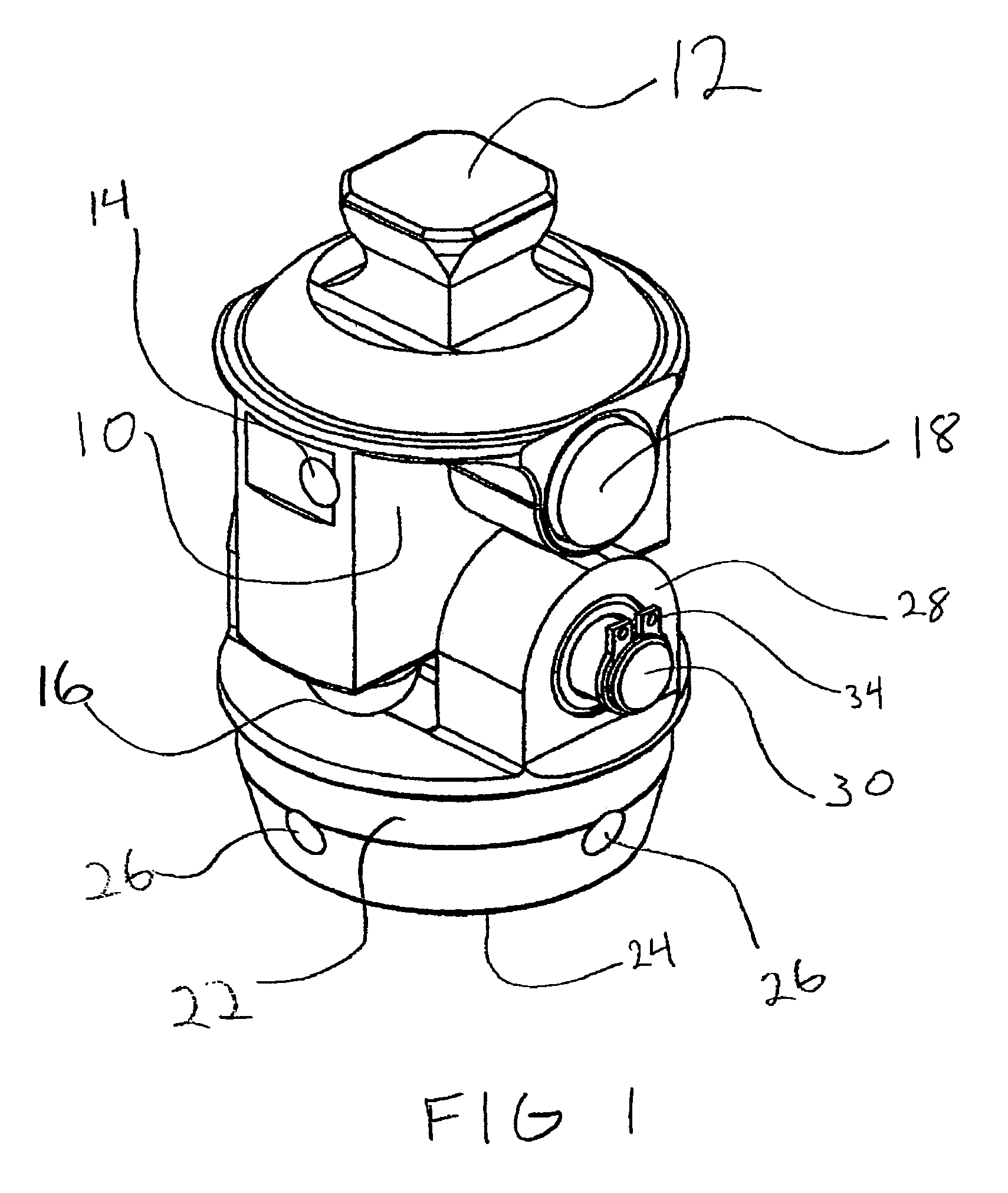
[0018]FIG. 1 shows a perspective view of an embodiment of the present invention. Upper support unit 10 includes a standardized male connector 12, which is well known in the art. A grease insertion port 14 is shown on one side of upper support unit 10. Another grease insertion port 15 (not shown) is on the opposite side of the grease insertion port 14. A set screw can be sealed in place in each grease insertion port after the desired amount of grease has been inserted into the internal valve and cylinder system discussed below. A piston 16 is shown protruding from the bottom of the upper support unit 10. Another piston 17 (not shown) is located parallel to and on the opposite side of the upper support unit 10 from piston 16. A valve control button 18 is shown on one side of upper support unit 10. This button 18 is connected to a valve control shaft 20 that is internal to the upper unit 10 and thus not shown in this figure.

[0019]Referring again to FIG. 1, a lower support unit 22 inclu...


PUM


Abstract

An adjusting mechanism alters the heel height on a prosthetic foot, and works independently of any articulating ankle joint or foot style, without changing the original dynamic alignment of a prosthetic leg. In a two chamber hydraulic closed system—a fluid material is allowed to flow through the two chambers by use of pistons that push the fluid material equally from one chamber to another until the desired heel height is obtained. Once the correct position is obtained, the ports are closed by use of a push button stop, which closes the ports and stops all transfer of fluid between the ports holding the heel in position during use.

Description

[0001]This application claims priority to U.S. Provisional Patent Application Ser. No. 60 / 525,289, titled: “Heel Height Adjusting Mechanism For A Prosthetic Foot,” filed Nov. 25, 2003, incorporated herein by reference.BACKGROUND OF THE INVENTION[0002]1. Field of the Invention[0003]The present invention relates to prosthetics, and more specifically, it relates to an adjusting mechanism for a prosthetic.[0004]2. Description of Related Art[0005]A variety of adjustable prosthesis joints are known; however, they are generally expensive to manufacture, complex and larger than desirable.[0006]For example, U.S. Pat. No. 5,957,981 claims an adjustable prosthesis joint to set the angular relation between an attachment socket for connecting the joint to a cooperating body member and a prosthesis detail, the prosthesis joint comprising a housing; a chamber disposed in the housing; an intermediate wall fixed within the chamber to subdivide the chamber into at least two communicating chamber port...

Claims


Application Information

Patent Timeline
Patent Type & Authority Patents(United States)
IPC IPC(8): F16D69/00A61F2/50A61F2/66A61F2/68A61F2/74A61F2/76
CPCA61F2/76A61F2/6607A61F2002/5006A61F2002/5018A61F2002/505A61F2002/6854A61F2002/745A61F2/74
Inventor VITALE, THOMAS N.HILL, DAVID A.
Owner THERMAL TECH
Why Eureka
Try Eureka